Conscientious sales engineer with demonstrated experience working in the machine and parts manufacturing industry. Ability to independently manage sales operations for commodities (engineering and manufacturing) and proficiency in quality customer service, international trade, and professional engineering project solution support. Great energy and great love into learning about processing, manufacturing.
Once you have configured your project details, your quotation will be automatically saved, ensuring you do not lose any progress. To access your saved quotation, simply navigate to the “My Quotes” section of our platform.
From here, you can continue editing your project information or review the quotation details to ensure everything is accurate and meets your requirements. You can also place an order directly from your saved quotation by following the simple steps provided on the platform.
Our auto-save feature ensures that you can easily pick up where you left off and make any necessary adjustments to your project details without starting over from scratch. We strive to make the quotation and ordering process as smooth as possible, so you can focus on your project without worrying about the logistics.
Yes, you can get a quotation without a 3D file. However, we may need to discuss the project further with you. If you do not have a 3D file for your parts, you can request a manual quotation that includes all relevant information and technical drawings.
Please keep in mind that manual quotations may take a little longer to assess since our team will need to personally review your project description and evaluate your technical drawings to determine the cost. Our AI engine is responsible for handling 3D files. We may have to request additional details if the information and drawings are insufficient.
We are more than happy to process manual quotations. However, if you require an instant online quotation, we recommend submitting a 3D file. Doing so will help us provide a faster and more accurate quotation.
XCD’s instant quotation platform can interpret various 3D CAD file types. However, if you are having trouble uploading your file, it may mean that it is not in a compatible format. If it’s still not uploading after confirming it is in one of our accepted formats, it could be because the file exceeds the 15MB size limit. Due to server limitations, we can only accept files of this size or smaller.
Another reason for uploading failure could be a weak internet connection, which can make it difficult to upload large files. We recommend trying again with a strong broadband connection. It is important to note that 3D files are the preferred format for starting the quotation process. However, if you do not have a suitable 3D file, you can request a manual quotation instead.
XCD accepts the following file formats for instant quotation: step, stp, stl, igs, iges, prt, sldprt, sat, x_t. The maximum file size for every format is 15MB. You can upload your 3D file to our platform by dragging and dropping the file into the designated area or by clicking the upload button and selecting the file from a folder on your computer.
Formats such as STL, which are mesh-based, are suitable for obtaining quotes for 3D printing services and urethane casting. The input unit may be in inches (in.) or millimeters (mm), depending on the export unit of the file.
Please note that native CAD assembly files do not have solid model information and cannot be loaded onto XCD’s platform. To ensure that part models are accurately quoted, please remove or suppress any multi-body features, such as installed inserts, before uploading them.
XCD is a one-stop shop for all your manufacturing needs, offering a wide range of services to take your product from concept to market-ready. Our services include everything from Design for rapid prototyping and low or high-volume production. With XCD, you have a reliable partner you can count on for everything.
Here are some of our key manufacturing services for prototyping and on-demand production:
CNC Machining
Injection Molding
Sheet Metal Fabrication
3D Printing
Vacuum Casting
Die Casting
Finishing Services
Our CNC machining services use advanced technologies and techniques to deliver high-quality, precise parts with quick turnaround times. Our injection molding services produce high-volume production runs of plastic parts with excellent repeatability and accuracy.
Our sheet metal fabrication services use various cutting, bending, and welding techniques to create complex shapes and designs from sheet metal. Our 3D printing services offer a quick and cost-effective way to produce parts using a variety of materials and techniques.
We also offer vacuum casting and die casting services for low-volume production runs of plastic and metal parts. Our finishing services include surface treatments, painting, anodizing, and other finishing techniques to give your parts the desired appearance and functionality.
This project was led by Lin, a personal educational initiative aimed at lifelong learning on a limited budget, with the goal of sharing the findings publicly.
Lin conducted a detailed study of the M-73 prismatic compass, a military-grade magnetic instrument used worldwide. His work documented the compass’s history, operation, maintenance, and repair—information not readily available elsewhere. As part of the project, he designed a custom precision mount to keep the compass stable for testing, alignment, and surveying.
Finding the right manufacturing partner was critical. Lin required a supplier capable of producing the mount from non-magnetic materials, with precise tolerances and the necessary surface finishes. After reviewing multiple options, he chose RapidDirect, the only supplier able to meet all specifications while keeping the project on budget and schedule.
Industry
Engineering
Product
Custom precision mount for the compass
Services Provided
Rapid prototyping services
Technology
CNC machining
Materials
Aluminum, Stainless steel
Surface Treatments
Anodizing, Brushed finish
The Challenges
The custom mount needed to be adapted to existing equipment that was not originally designed for this purpose, while ensuring maximum stability and precision under outdoor and suboptimal conditions. In addition, the material had to be non-magnetic to prevent any interference with the compass needle.
“I needed a partner who could produce a CNC-machined part that met very specific requirements for material and precision,” Lin said. “RapidDirect was the only supplier able to deliver what I needed on time and within budget.”
The Solution
RapidDirect’s engineering team reviewed the design and quickly recognized the project’s unique requirements. We:
Provided efficient order handling and a detailed manufacturability assessment
Offered design adjustment suggestions to improve machining feasibility while preserving accuracy
Produced the components through CNC machining with ISO 2768M tolerances
Applied black matte anodizing on aluminum parts for durability and a brushed finish on stainless steel brackets
Delivered parts with precise threaded features and full inspection reports
Lin highlighted the experience:
“RapidDirect enabled me to proceed with my project faster because of its efficient processing of orders, including prompt assessment of the machinability of my part and suggestions for modifications.”
Within just two weeks, Lin received the finished components, ready for validation and field testing.
RapidDirect’s online platform is straightforward and easy to use from uploading parts to selecting fabrication options, specifying special requirements, and managing payment and shipping. They were the only company able to produce my challenging non-magnetic design with the required materials and finishes, all at a reasonable cost and with a quick turnaround. Their customer service was also fast and responsive in addressing any questions or issues.
Lin
A Scientific Officer
The Results
The collaboration with RapidDirect allowed Lin to create a precision mount that proved reliable in field tests. Rapid CNC machining enabled him to complete validation quickly and cost-effectively while staying within budget. With high machining accuracy and durable material quality, the mount met strict field requirements and provided a dependable solution for both practical use and ongoing research.
My specially designed tripod land survey mounting blocks for the M-73 prismatic compass are being deployed in treacherous terrain on Singapore’s highest mountain (16,300 cm) in National Parks Board’s Bukit Timah Nature Reserve. Each high-strength block of solid material weighs 1 kg and was precision-machined by RapidDirect Co., Ltd who have also supplied high-quality experimental “missile parts” for my hyperphoton launch system announced earlier.
Lin
A Scientific Officer
Looking Ahead
Building on this success, Lin plans to develop a second-generation bracket with improved centering precision and clamping stability. He is also considering the design of a dedicated adapter for compass needle calibration.
Looking ahead, Lin intends to continue working with RapidDirect on future iterations of the project. With a reliable custom manufacturing partner in place, he is confident about further refining the design and expanding the scope of his educational work.
Estimating the exact cost of rotational parts without a formal quote often stalls project timelines and budgeting. Underestimating your machining budget at the design phase usually leads to painful, forced redesigns right before production. Having analyzed thousands of rotational parts and their cost drivers, we broke down exactly how materials, tolerances, and machine time impact your bottom line. Engineers and procurement teams looking for accurate estimates can use this guide to forecast their custom cnc turning cost immediately. Here is the baseline calculator and the exact breakdown you need to optimize your next order.
Core Affect CNC Turning Cost Components
Understanding the exact breakdown of your manufacturing bill helps you identify where to cut costs.
Machine Time (The Largest Variable)
Machine time dictates the majority of your total expense. Complex geometries require slower feed rates. This increases total cycle time and drives up the price.
Standard 2-axis lathes cost less per hour than multi-axis mill-turn centers. Swiss-type lathes operate at different hourly rates but machine long, slender shafts much faster.
Raw Material Expenses
Raw material prices scale based on the specific alloy and the required billet size. Using a steel cnc turning cost calculator requires you to factor in material waste.
Oversized bar stock results in heavy material removal and increased chip waste. Extremely hard materials like titanium also incur a high raw material premium.
Tooling and Wear
Machining hard metals quickly degrades cutting tools. Carbide, ceramic, and diamond (PCD) inserts represent a significant consumable cost.
When turning stainless steel or aerospace alloys, tool wear accelerates rapidly. The factory passes these replacement costs directly to the buyer.
Setup and Labor
Setup costs include programming the toolpaths, preparing the stock, and configuring the machine. For low-volume prototypes, these fixed costs are absorbed by just a few parts.
In mass production, setup time is amortized across thousands of units. This makes the individual piece price drop significantly.
Key Variables That Drive CNC Turning Pricing
Several distinct factors determine the final number on your quote.
Part Complexity: Deep internal bores and thin walls require specialized strategies and slow feed rates.
Tolerances: The standard CNC tolerance is ISO 2768-m (+/- 0.1mm). Requesting precision tolerances of +/- 0.01mm requires slower cutting and frequent tool changes. RapidDirect is capable of high precision up to ±0.003 mm for critical applications.
Batch Size: Ordering a single prototype costs substantially more per unit than a production run of 5,000 parts.
Material Selection: Plastics and aluminum machine easily. Steels and superalloys require more machine time and burn through tools faster.
Delivery Speed: Standard CNC prototyping lead times are 3-5 days. Expedited orders incur rush fees to cover overtime and rearranged production schedules.
Certifications: Medical or automotive parts requiring ISO 13485 or IATF 16949 compliance add administrative and inspection overhead.
CNC Turning Material Cost Multipliers for Faster Estimating
Use this lookup table to adjust your baseline estimates based on material selection.
Material Category
Machinability
Relative Cost Multiplier
6061 Aluminum
High
1.0x (Baseline)
Plastics (POM/PEEK)
Very High
1.1x – 1.5x
Carbon Steel
Medium
1.3x
Stainless Steel
Low
1.6x – 2.0x
Titanium Alloys
Very Low
3.0x – 4.0x+
CNC Turning Cost vs. Other Machining Processes
Procurement teams often weigh turning against other manufacturing methods.
Turning vs. Milling
For axially symmetric parts, turning is significantly faster and cheaper than milling. A lathe continuously cuts the rotating part, removing material highly efficiently. Milling the same cylindrical profile requires complex 3D interpolation and takes much longer.
Standard Lathe vs. Mill-Turn
Standard lathes handle basic cylindrical profiles efficiently. If your part features radial holes or milled flats, a standard lathe requires secondary operations on a milling machine.
Mill-turn centers handle both operations in a single setup. While their hourly rate is higher, the eliminated secondary setup time often results in a lower total cost. RapidDirect offers comprehensive 3/4/5-Axis Milling, Turning, and Mill-Turn services to match the exact needs of your part.
DFM Strategies to Reduce CNC Turning Cost
Engineers can drastically reduce their machining bills by optimizing their CAD files.
Pro Tip: Keep internal corner radii as large as possible. Small internal radii require tiny boring bars that vibrate easily and require very slow feed rates.
Relax Tolerances: Only apply tight tolerances to critical mating surfaces. Leave non-functional features at the standard +/- 0.1mm ISO 2768-m tolerance.
Standardize Threads: Use standard metric or imperial thread sizes. Custom threads require specialized cutting tools and custom programming.
Optimize Wall Thickness: Avoid designing extremely thin walls. Thin walls deflect under cutting forces and require multiple, slow, low-pressure passes.
Simplify Surface Finishes: Specify high surface finishes (Ra 0.8) only where necessary. A standard machined finish (Ra 3.2) requires far less machine time.
Smart Material Swaps: If a part does not experience extreme stress or corrosive environments, switch from stainless steel to aluminum.
How to Estimate Your Precision CNC Turning Cost
You can manually forecast the price using a standard manufacturing formula.
To get an exact figure without manual math, use a digital cnc turning costing calculator. Better yet, submit your drawings for automated quoting.
RFQ Preparation Checklist
Providing incomplete data forces suppliers to pad their quotes for risk. Always include:
Complete 3D STEP files and 2D PDF drawings.
Clear tolerance callouts and surface roughness (Ra) requirements.
Exact material grades (e.g., Al 6061-T6, not just “Aluminum”).
Target order quantities and required lead times.
Required material certifications or inspection reports.
Sourcing CNC Turning with RapidDirect
Traditional quoting takes days and relies on manual estimation. RapidDirect operates an intelligent online platform that features an AI-driven quoting engine, returning prices in minutes.
Our platform provides instant quoting alongside free DFM reports to help you optimize costs immediately. We maintain our headquarters and factories in Shenzhen, China. This location gives us direct access to the supply chain and a lower cost structure, passing the savings on to you.
We hold ISO 9001, 13485, 14001, and IATF 16949 certifications, ensuring robust quality control. You can track your orders in real time, guaranteeing transparency from production to final global shipping.
In CNC machining and custom manufacturing, surface roughness is not merely an aesthetic choice—it is a critical cost driver. Over-specifying tolerances and Ra values is the leading cause of artificially inflated part costs, often increasing manufacturing expenses by over 30%. If surface texture matters to your product’s sealing, friction, or coating adhesion, this guide will help you interpret standard symbols and apply the right specifications without breaking your budget.
This article provides the most comprehensive surface roughness chart and explains how to balance mechanical performance with cost-effective manufacturing. Whether you are sealing a high-pressure valve or prepping a sheet metal chassis for powder coating, RapidDirect’s AI DFM engine can analyze your CAD file in seconds to identify cost spikes caused by overly strict roughness callouts.
👉Jump to Surface Finish Conversion Chart
What is Surface Finish?
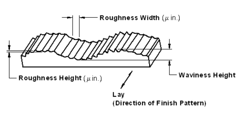
Before we go into the surface finish chart, let’s understand what surface finish entails. Surface finish refers to the process of altering a metal’s surface that involves removing, adding, or reshaping. Surface texture describes a product’s complete surface profile, defined by its roughness, waviness, and lay.
The surface roughness is the measure of the total spaced irregularities on the surface. Whenever machinists talk about “surface finish,” they often refer to surface roughness.
Waviness refers to the warped surface whose spacing is greater than that of surface roughness length. Lay refers to the direction the predominant surface pattern takes. Machinists often determine the lay by the methods used for the surface.
Why is Surface Finish Important in Engineering Processes?
Surface roughness plays a very crucial role in determining how a product reacts to its environment. The finish of a product indicates the performance of its components. Also, the level of roughness may affect the effectiveness of a product.
This depends on the application of such a product. Engineers and manufacturers must maintain surface finish at all times. It helps to produce consistent processes and reliable products.
Surface measurements also help maintain control of manufacturing. It is very useful whenever there’s a need for surface engineering.
Different surface finishes have a variety of effects. The easiest way to get the desired surface finish is to compare it with the surface finish standards. Surface finish can help in the following ways and more:
Incredibly important for corrosion and chemical resistant effects.
It offers a specific visual appeal to the product.
Helps with the adhesion of coatings and paints.
Eliminates surface defects.
Improves conductivity and adds surface electrical conductions.
Increases product’s strength against wear while minimizing friction effects.
RapidDirect is a leading on-demand manufacturing company providing high-quality surface finishing services. We offer 17+ surface finishing processes, including anodizing, powder coating, sandblasting, and more — all designed to enhance both the appearance and performance of your components.
Whether you need a smooth cosmetic look or precise functional finish, our solutions help you achieve the desired Ra surface roughness and durability.
Ready to Start Your Project?
Get Instant Quote
To learn more about surface finishing, read our guide to plastic injection molding surface finish options and read our article about getting the best CNC machining surface finish for your products.
The Broker Trap: Why “Standard” Surface Finish Often Fails
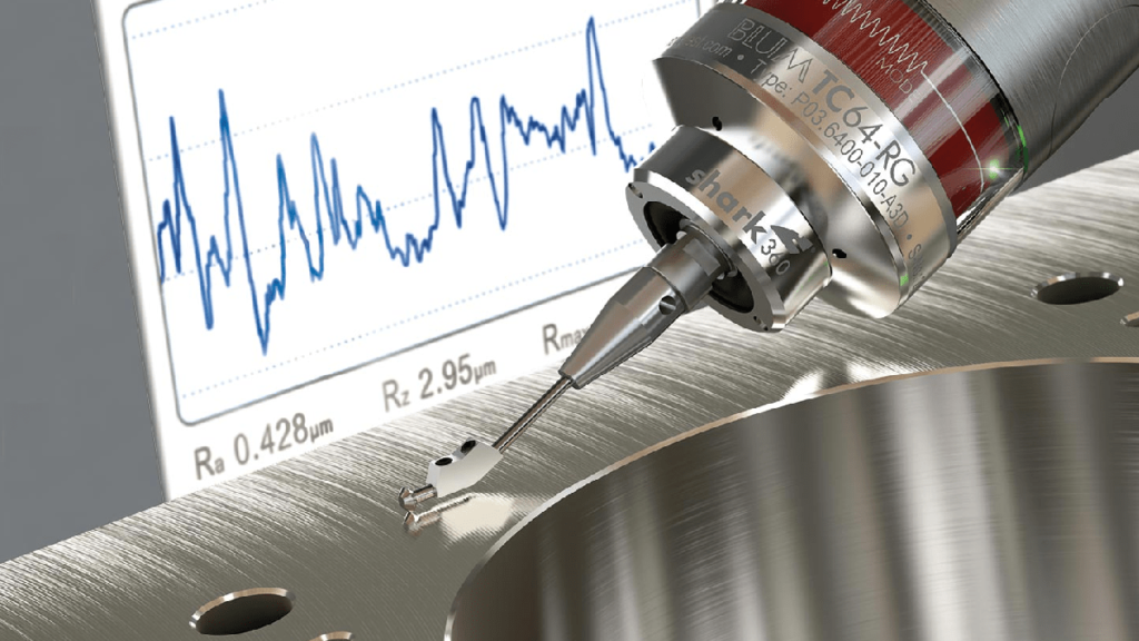
Many digital manufacturing platforms operate as brokers, routing your CAD files to unvetted workshops that lack digital profilometers. Relying on visual or tactile “fingernail checks” to meet a Ra 0.8 µm requirement is catastrophic for precision components such as hydraulic seals, bearing seats, or aerospace housings.
At RapidDirect’s 20,000㎡ proprietary facility, we eliminate this guesswork. We use ZEISS and Mitutoyo surface roughness testers, along with comprehensive CMM verification, to physically verify your specified Ra values. By combining this strict metrology with our high-rigidity 5-axis CNC machines, we consistently achieve ±0.003 mm geometric tolerances and flawless surface finishes, preventing leaks or assembly failures.
How to Measure Surface Roughness
Surface roughness is a calculation of the relative smoothness of a surface’s profile. The numeric parameter – Ra – represents the average roughness. The Ra surface roughness chart shows the arithmetic average of surface heights measured across a surface.
As already mentioned, there are three basic components of a surface, roughness, waviness, and lay. Therefore, different factors are affecting the characteristics of surface geometry.
Likewise, there are several measuring systems for surface roughness. The systems include:
Direct measurement methods
Non-contact methods
Comparison methods
In-process methods
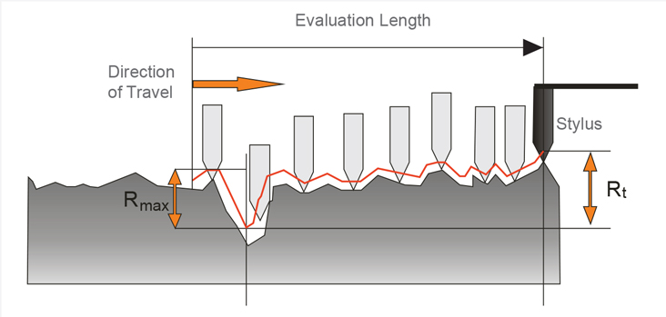
The direct measurement methods measure surface roughness using a stylus. That involves drawing the stylus perpendicular to the surface. The machinist then uses a registered profile to determine roughness parameters.
Non-contact methods involve the use of light or sound instead. Optical instruments like white light and confocal replace the stylus. These instruments use different principles for measurement. The physical probes can then be switched with optical sensors or microscopes.
First, the instrument used will send an ultrasonic pulse to the surface. Then, there’ll be altering and reflection of the sound waves back to the device. You can then assess the reflected waves to determine roughness parameters.
Comparison techniques employ surface roughness samples. These samples are generated by the equipment or process. Then, the manufacturer uses tactile and visual senses to compare the results against the surface of known roughness parameters.
An example of an in-process technique is inductance. This method helps to evaluate surface roughness using magnetic materials. The inductance pickup uses electromagnetic energy to gauge the distance to the surface. Then, the parametric value determined can help find out comparative roughness parameters.
Various Methods of Measuring Surface Roughness
There are different methods and equipment involved in measuring surface roughness. The methods can fall into three categories. They are:
Profiling Techniques. This involves the measurement of the surface using a high-resolution probe. In this process, you need to think more of a phonograph needle in line with sensitivity. A typical CNC probe may not be as effective.
Area Techniques. These techniques measure a finite area of the surface. The measurement offers a statistical average of peaks and troughs in the surface. Some examples of these techniques include ultrasonic scattering, optical scattering, capacitance probes, and more. It is easier to automate and execute with area techniques.
Microscopy Techniques. These qualitative techniques rely on measuring contrasts. The results provide relevant information about peaks and valleys on surfaces.
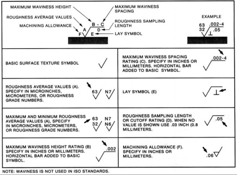
Surface Roughness Symbols Chart and Abbreviations
When you search for machining surface finish symbols on your favorite browser, you would notice a range of abbreviations. These include Ra, Rsk, Rq, Rku, Rz, and more. They are units used in measuring surface finish.
Ra – Average Surface Roughness
While most people refer to Ra as Center Line Average or Arithmetic Average, it is the average roughness between a roughness profile and the mean line. This is the most commonly used parameter for surface finish. The Ra surface roughness scale, often presented as a surface finish chart, shows typical Ra values used in engineering and manufacturing applications.
Rmax – Vertical Distance from Peak to Valley
This roughness parameter is best used for anomalies such as burrs and scratches. It may not be obvious with the Ra surface finish chart though. However, Rmax is a lot more sensitive to those anomalies.
Rz – Average Maximum Height of the Profile
Unlike Ra, Rz measures the average values of the five largest differences between peaks and valleys. The measurement is done using five sampling lengths, and it helps to eliminate error since Ra is quite insensitive to some extremes.
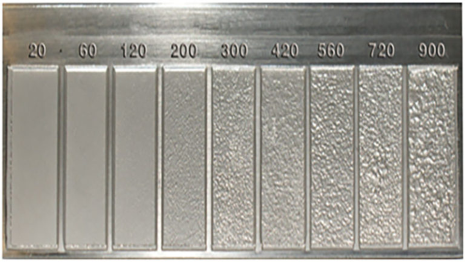
Surface Roughness Chart
The machining surface finish chart offers important guidelines for measuring standard surface finish parameters. Manufacturers always use it as a reference material to ensure quality in the manufacturing process.
20 to 900 RMS
There are different processes in examining the machining surface finish chart. As a result, it becomes challenging to pick the best process based on the performance of the product. However, the most robust is the use of the surface finish conversion chart.
1. Surface Finish Conversion Chart
In this section, you’ll find a table for the surface finish conversion chart. This table serves as a surface roughness comparison chart, helping you compare different roughness scales—such as Ra, Rz, and RMS—across various manufacturing standards and processes. Before diving into the chart, let’s go through some of the abbreviations you’ll encounter.
Ra = Roughness Average
RMS = Root Mean Square
CLA = Center Line Average
Rt = Roughness Total
N = New ISO (Grade) Scale Numbers
Cut-off Length = Length Required for Sample
Ra(micrometers)
Ra(microinches)
RMS(microinches)
CLA(N)
Rt(microns)
N
Cut-off Length(inches)
0.025
1
1.1
1
0.3
1
0.003
0.05
2
2.2
2
0.5
2
0.01
0.1
4
4.4
4
0.8
3
0.01
0.2
8
8.8
8
1.2
4
0.01
0.4
16
17.6
16
2.0
5
0.01
0.8
32
32.5
32
4.0
6
0.03
1.6
63
64.3
63
8.0
7
0.03
3.2
125
137.5
125
13
8
0.1
6.3
250
275
250
25
9
0.1
12.5
500
550
500
50
10
0.1
25.0
1000
1100
1000
100
11
0.3
50.0
2000
2200
2000
200
12
0.3
2. Surface Roughness ChartCheat Sheet
This surface finish ‘cheat sheet’ is a super handy tool to help you better understand the various surface finishes available.
For hardware product teams navigating the transition from early concept design to low-volume manufacturing, traditional subtractive machining and rapid injection molding often present rigid financial and physical bottlenecks. Selective Laser Sintering (SLS) bypasses these barriers entirely. By producing highly complex, structurally sound components without the need for fixed tooling or sacrificial support structures, sls printing has established itself as the undisputed bridge between functional rapid prototyping and agile end-use production.
This comprehensive guide is designed for senior mechanical engineers, R&D directors, and NPI sourcing managers. It delves into the underlying physics of the sls process, details the thermomechanical properties of industrial polymer powders, resolves industry misconceptions surrounding “SLS metal,” and outlines how to leverage factory-direct 3D nesting to drive down your operational expenses (OpEx).
What is Selective Laser Sintering (SLS)?
Selective Laser Sintering is a highly advanced industrial powder bed fusion (PBF) technology. At its core, SLS utilizes a high-powered CO2 laser to selectively fuse (sinter) micro-particles of thermoplastic polymer powder into a solid, three-dimensional structure based on a digital CAD file.
Unlike extrusion-based technologies (like FDM) that suffer from weak layer-line adhesion, the sls process yields parts with near-isotropic mechanical properties. Because the polymer particles are thermally fused at the molecular level, SLS components exhibit robust tensile strength and durability across the X, Y, and Z axes. This structural integrity elevates sls prototypingbeyond mere visual mockups, enabling rigorous functional testing—such as dynamic fluid routing, high-stress snap-fit engagement, and live mechanical assemblies—in real-world operating environments.
How the SLS Process Works: The Physics of Powder Bed Fusion
The industrial SLS process is a delicate, highly calibrated thermodynamic cycle.
Thermal Pre-Heating:Before the laser fires, the internal build chamber and the entire bed of polymer powder are heated to a precise temperature just below the specific melting point of the material. This ambient pre-heating ensures that the laser only needs to deliver a minimal burst of energy to push the target particles across their phase-change threshold, preventing severe thermal shock.
Selective Laser Fusion:A highly calibrated CO2 laser traces the exact cross-sectional geometry of the part, fusing the powder particles together to form a solid layer.
Z-Axis Indexing and Recoating:The build platform lowers by a single layer fraction (typically 100 microns), and a recoater blade sweeps a fresh, uniform layer of powder across the bed.
Controlled Cooling:Once the entire build volume is complete, the chamber undergoes a meticulously slow, controlled cooling phase. Rushing this cooling process results in rapid, uneven volumetric shrinkage, which causes severe part warpage and dimensional distortion.
The Physics of No-Support: 3D Batch Nesting
The most defining economic and geometric advantage of selective laser sintering is its lack of physical support structures. Because the fused part is completely encased and suspended within the dense bed of unsintered powder, the powder itself acts as a natural, uniform support matrix.
This unlocks unprecedented geometric freedom: engineers can design complex interlocking gears, internal lattice structures, and deep undercut cavities without worrying about post-machining accessibility. Economically, this “self-supporting” environment allows for dense 3D Batch Nesting. Manufacturing engineers can stack hundreds of distinct parts throughout the X, Y, and Z axes of the build chamber (optimizing the packing density typically between 10% and 15%). This maximum utilization of machine space drastically drives down the machine-hour cost allocated to each individual part.
Clarifying the Myth: “SLS Metal Printing” vs. Polymer SLS
In industrial procurement, terminology confusion can lead to severe project delays. A frequent point of confusion among engineers is the term SLS metal printing.
Strictly speaking, SLS is exclusively reserved for thermoplastic polymers (such as Nylon PA12, PA11, and TPU elastomers). The term “SLS Metal” is an outdated or misapplied legacy term. If you require high-density, load-bearing metal components, you are looking for Direct Metal Laser Sintering (DMLS) or Selective Laser Melting (SLM), which utilize fiber lasers to process titanium, stainless steel, or aluminum.
(Note: If your application requires extreme thermal resistance or metal structural properties, please consult our [DMLS vs. SLM Metal AM Guide].)
Industrial SLS Materials: Beyond Basic Plastics
Industrial SLS platforms process highly engineered thermoplastic powders designed to mirror the mechanical properties of injection-molded counterparts.
Industrial SLS Polymer Properties Matrix
Industrial SLS Materials
Material Grade
Key Mechanical Advantage
Tensile Strength / Flexibility
Ideal Application
Nylon 12 (PA12)
The industry standard; excellent dimensional stability, low moisture absorption, high density.
High tensile strength (~48 MPa), rigid but tough.
General sls prototyping, complex housings, automotive ducting, snap-fit enclosures.
Nylon 11 (PA11)
Superior impact resistance, highly ductile, excellent fatigue limits for cyclic loading.
High elongation at break, highly flexible without fracturing.
Living hinges, impact-resistant drone chassis, customized orthotics, crash-test components.
PA12 Glass-Filled (GF)
Increased structural stiffness, superior thermal stability, high wear resistance.
Extreme rigidity, elevated Heat Deflection Temperature (HDT).
Engine bay tooling, high-temp fluid manifolds, heavy-duty mechanical brackets.
PA11 Carbon-Fiber (CF)
Exceptional strength-to-weight ratio, high electrostatic discharge (ESD) potential.
Because the SLS process requires zero tooling capital expenditure (CapEx), it dominates the economic break-even curve for low-to-medium volume runs.
For quantities ranging from 1 to 1,000 units, scaling your hardware via SLS is exponentially more cost-effective than cutting an aluminum or P20 steel injection mold. By aggressively optimizing the build volume through 3D nesting, sourcing managers can achieve an incredibly low per-part OpEx. Furthermore, if market feedback dictates a design change at unit 500, engineers simply upload a revised CAD file; there is no $10,000 tooling penalty to modify hardened steel. This extreme agility makes SLS the ultimate bridge-manufacturing technology.
DFM Rules and Best Practices for SLS 3D Printing
While SLS offers immense geometric freedom, engineers must still adhere to strict Design for Manufacturability (DFM) principles to prevent thermal defects.
DFM Rules and Best Practices for SLS 3D Printing
Hollow Parts and Powder Removal
To reduce part weight and save on premium powder costs, thick components should always be modeled as hollow shells. However, because the part is suspended in powder, the internal cavity will be packed with unsintered material. Engineers must design at least two escape holes(minimum 3.0mm diameter) into the geometry. This allows technicians to utilize compressed air to blow out the heavy “dead-weight” powder trapped inside the core during post-processing.
Shrinkage, Warping, and Oversintering
Although the cooling phase is tightly controlled, dense blocks of solid polymer still retain intense thermal mass. If a design features an abrupt transition from a thin wall (e.g., 1.0mm) to a massive, thick solid boss, the thick section will remain hot and contract long after the thin wall has solidified. This localized shrinkage causes severe geometric warping and dimensional drift. Additionally, tight internal channels must be sized correctly to prevent “oversintering”—a defect where ambient heat accidentally fuses loose powder to the internal walls, plugging the channel permanently.
Scaling with RapidDirect: Your Factory-Direct SLS Partner
Sourcing functional SLS components through decentralized broker networks introduces severe quality control risks. Routing confidential CAD files to unvetted sub-tier shops often results in parts printed on uncalibrated machines that fail to execute the controlled cooling cycles required to prevent thermal warpage. RapidDirect eliminates these supply chain vulnerabilities as a fully integrated, factory-direct manufacturer. Across our 20,000㎡ advanced facility, we operate high-capacity industrial SLS print farms under strict quality management protocols. Our in-house manufacturing experts handle every operational step, from strict environmental controls to professional post-processing like precision bead-blasting and automated tumbling.
When you upload your files to our ecosystem, our proprietary AI DFM engine automatically audits your CAD geometry in seconds—identifying trapped powder risks and dangerous wall thickness transitions before production begins. To secure your NPI timeline and ensure strict material traceability, upload your CAD file to our instant quote platform today. You will receive a transparent quotation and a complimentary DFM geometric verification report. Partner with our in-house engineering team and leverage our comprehensive 3d printing service and specialized SLS 3d printing service to scale your product development with absolute factory control.
Frequently Asked Questions (FAQ)
What are the limitations of SLS 3D printing?
Due to the nature of the raw powder and the laser sintering physics, as-printed SLS components inherently feature a slightly rough, porous, and matte surface finish (resembling a sugar cube). If a perfectly smooth or watertight surface is required, extensive post-processing (such as vapor smoothing or urethane clear-coating) is necessary. Additionally, extremely fine, fragile features or incredibly thin walls (below 0.8mm) may fail to resolve or snap during the powder excavation process.
SLA versus SLS: Choosing the right 3D printing process?
SLA utilizes liquid photopolymer resins to produce completely watertight, highly detailed components with smooth, SPI A-2 grade surface finishes; however, the parts can be brittle and degrade under UV light. SLSutilizes durable thermoplastic powders to produce impact-resistant, highly functional parts with complex, support-free geometries, making it the superior choice for high-stress mechanical testing, snap-fits, and bridge manufacturing runs.
Verifying if a ±0.05 mm callout is achievable on a fiber laser or if it requires CNC milling is a constant balancing act for mechanical engineers and procurement managers. Guessing these baseline capabilities leads to assembly failures from loose fits or exponential cost increases from over-tolerancing. Having manufactured thousands of precision sheet metal components, we tracked the exact dimensional deviations across various materials and plate thicknesses. Here are the definitive laser cutting tolerance charts and DFM guidelines you need to validate your CAD drawings immediately.
Standard Laser Cutting Tolerances (The Baseline)
When a specific dimensional deviation is not explicitly called out on a CAD drawing, manufacturers default to established international standards. The most critical general tolerance for laser cutting is the DIN ISO 2768 standard. RapidDirect and other professional fabricators typically execute the ISO 2768-1 m (medium) class for all sheet metal laser cut tolerances unless otherwise specified.
Laser Cutting Tolerance Chart (ISO 2768-1 m – Medium Class)
Nominal Dimension (mm)
Standard Tolerance (mm)
Precision Tolerance (f-class) (mm)
< 0.5
±0.10
±0.10
0.5 to 3
±0.10
±0.05
3 to 6
±0.20
±0.10
6 to 30
±0.30
±0.15
30 to 120
±0.50
±0.20
120 to 400
±0.80
±0.30
400 to 1000
±1.20
±0.50
For general projects, you can expect typical laser cutting tolerances to hold within ±0.1 mm to ±0.2 mm (roughly ±0.005 inches) for linear dimensions under 100 mm. For ultra-precision requirements, the fine (f) class tightening to ±0.05 mm is possible. Reaching this level requires high-end fiber laser equipment and optimal operating conditions.
How Material Thickness Impacts Laser Cutting Tolerances
The tolerance of laser cutting is not static; it scales directly with the thickness of the plate. As the material gets thicker, the laser beam diffuses, creating a wider heat-affected zone (HAZ). This phenomenon introduces a slight taper to the cut edge, known as kerf taper.
The DIN EN ISO 9013-1 standard defines specific thermal cutting tolerances based on plate thickness. Fiber laser cutting tolerances stainless steel parts at 1 mm thick will naturally be much tighter than a 15 mm thick carbon steel plate. For steel plates between 0 mm and 25 mm, the allowable deviations expand progressively from ±0.075 mm up to ±3.25 mm. You must widen your acceptable laser cutting tolerances mm by mm as you scale up your material gauge.
Raw Material Tolerances (The Hidden Variable)
Engineers often overlook the inherent physical limitations of the raw sheet metal itself. Before the laser even fires, the material brings its own baseline deviations. Sheet metal is never perfectly flat.
Standard cold-rolled steel plates carry a flatness tolerance mandated by DIN EN 10259. A 2.0 mm thick sheet naturally has a flatness variation of ±0.10 mm. If your design requires a laser cutting profile tolerance tighter than the raw material’s inherent flatness, the part will fail inspection.
DFM Rules of Thumb for Laser Cut Hole Tolerance
Designing holes and slots for laser cutting requires specific spacing to maintain structural integrity. If holes are placed too close to the edge, the concentrated heat will warp the material and destroy the laser cut hole diameter tolerance.
Rule of Thumb 1: The minimum hole diameter should equal the material thickness (1:1 ratio).
Rule of Thumb 2: Keep the distance from the center of a hole to the plate edge at least 1x the hole diameter.
Rule of Thumb 3: For slots, ensure the distance to the edge is at least 1.5x the slot width.
To maintain strict laser cut part tolerances, web widths (the material between two cuts) should never drop below 50% of the material thickness. Upload your STEP or DXF files to RapidDirect’s AI-driven platform to receive an instant DFM report that flags these specific spacing violations automatically.
Applying a blanket ultra-tight tolerance to an entire drawing is a common engineering mistake. High precision demands slower cutting speeds, which reduces machine throughput. It also requires advanced inspection equipment like Coordinate Measuring Machines (CMMs) to verify the laser cutting positional tolerance.
These factors can inflate production costs by 300% to 500%. You should only apply tight tolerances to critical mating surfaces or functional assembly points. Use standard laser cut steel tolerances for all non-critical boundaries.
Laser Cutting Equipment Capabilities: Fiber vs. CO2
The type of machinery used dictates the final precision of your parts. You must align your design expectations with the correct manufacturing technology.
Fiber Lasers: The industry standard for metal. They deliver a microscopic focal spot and cut rapidly. They comfortably hold laser cutting aluminium tolerances and stainless steel tolerances down to ±0.05 mm to ±0.2 mm.
CO2 Lasers: Better suited for thick carbon steel, wood, and plastics. Their laser cut tolerances typically range from ±0.1 mm to ±0.5 mm.
Final Takeaway
Specifying the correct tolerance of laser cutting protects your budget while ensuring your parts fit perfectly on the assembly line. Rely on ISO 2768-m for general dimensions, widen your acceptable deviations for thicker plates, and never demand CNC-level precision from a thermal cutting process unless absolutely necessary.
If you have a CAD file ready for production, upload it to the RapidDirect platform. Our automated quoting engine will analyze your geometry, provide an exact price within minutes, and generate a comprehensive DFM report to guarantee your tolerances are production-ready.