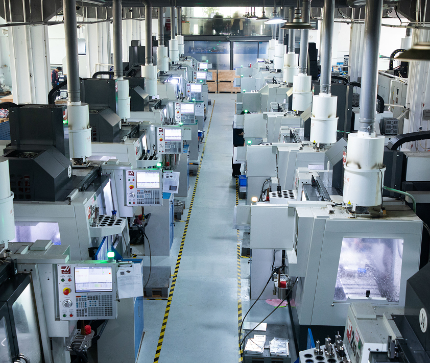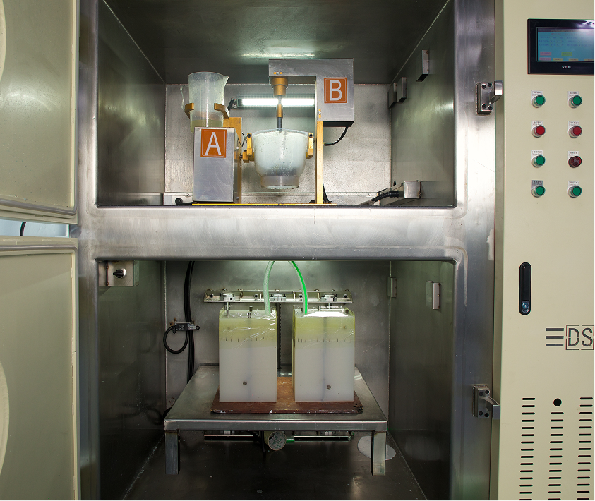

Verifying if a ±0.05 mm callout is achievable on a fiber laser or if it requires CNC milling is a constant balancing act for mechanical engineers and procurement managers. Guessing these baseline capabilities leads to assembly failures from loose fits or exponential cost increases from over-tolerancing. Having manufactured thousands of precision sheet metal components, we tracked the exact dimensional deviations across various materials and plate thicknesses. Here are the definitive laser cutting tolerance charts and DFM guidelines you need to validate your CAD drawings immediately.
Standard Laser Cutting Tolerances (The Baseline)
When a specific dimensional deviation is not explicitly called out on a CAD drawing, manufacturers default to established international standards. The most critical general tolerance for laser cutting is the DIN ISO 2768 standard. RapidDirect and other professional fabricators typically execute the ISO 2768-1 m (medium) class for all sheet metal laser cut tolerances unless otherwise specified.
Laser Cutting Tolerance Chart (ISO 2768-1 m – Medium Class)
| Nominal Dimension (mm) | Standard Tolerance (mm) | Precision Tolerance (f-class) (mm) |
| < 0.5 | ±0.10 | ±0.10 |
| 0.5 to 3 | ±0.10 | ±0.05 |
| 3 to 6 | ±0.20 | ±0.10 |
| 6 to 30 | ±0.30 | ±0.15 |
| 30 to 120 | ±0.50 | ±0.20 |
| 120 to 400 | ±0.80 | ±0.30 |
| 400 to 1000 | ±1.20 | ±0.50 |
For general projects, you can expect typical laser cutting tolerances to hold within ±0.1 mm to ±0.2 mm (roughly ±0.005 inches) for linear dimensions under 100 mm. For ultra-precision requirements, the fine (f) class tightening to ±0.05 mm is possible. Reaching this level requires high-end fiber laser equipment and optimal operating conditions.
How Material Thickness Impacts Laser Cutting Tolerances
The tolerance of laser cutting is not static; it scales directly with the thickness of the plate. As the material gets thicker, the laser beam diffuses, creating a wider heat-affected zone (HAZ). This phenomenon introduces a slight taper to the cut edge, known as kerf taper.

The DIN EN ISO 9013-1 standard defines specific thermal cutting tolerances based on plate thickness. Fiber laser cutting tolerances stainless steel parts at 1 mm thick will naturally be much tighter than a 15 mm thick carbon steel plate. For steel plates between 0 mm and 25 mm, the allowable deviations expand progressively from ±0.075 mm up to ±3.25 mm. You must widen your acceptable laser cutting tolerances mm by mm as you scale up your material gauge.
Raw Material Tolerances (The Hidden Variable)

Engineers often overlook the inherent physical limitations of the raw sheet metal itself. Before the laser even fires, the material brings its own baseline deviations. Sheet metal is never perfectly flat.
Standard cold-rolled steel plates carry a flatness tolerance mandated by DIN EN 10259. A 2.0 mm thick sheet naturally has a flatness variation of ±0.10 mm. If your design requires a laser cutting profile tolerance tighter than the raw material’s inherent flatness, the part will fail inspection.
DFM Rules of Thumb for Laser Cut Hole Tolerance
Designing holes and slots for laser cutting requires specific spacing to maintain structural integrity. If holes are placed too close to the edge, the concentrated heat will warp the material and destroy the laser cut hole diameter tolerance.
- Rule of Thumb 1: The minimum hole diameter should equal the material thickness (1:1 ratio).
- Rule of Thumb 2: Keep the distance from the center of a hole to the plate edge at least 1x the hole diameter.
- Rule of Thumb 3: For slots, ensure the distance to the edge is at least 1.5x the slot width.
To maintain strict laser cut part tolerances, web widths (the material between two cuts) should never drop below 50% of the material thickness. Upload your STEP or DXF files to RapidDirect’s AI-driven platform to receive an instant DFM report that flags these specific spacing violations automatically.
Laser Cutting Tolerances Cost: Avoid Over-Tolerancing
Applying a blanket ultra-tight tolerance to an entire drawing is a common engineering mistake. High precision demands slower cutting speeds, which reduces machine throughput. It also requires advanced inspection equipment like Coordinate Measuring Machines (CMMs) to verify the laser cutting positional tolerance.
These factors can inflate production costs by 300% to 500%. You should only apply tight tolerances to critical mating surfaces or functional assembly points. Use standard laser cut steel tolerances for all non-critical boundaries.
Laser Cutting Equipment Capabilities: Fiber vs. CO2
The type of machinery used dictates the final precision of your parts. You must align your design expectations with the correct manufacturing technology.
- Fiber Lasers: The industry standard for metal. They deliver a microscopic focal spot and cut rapidly. They comfortably hold laser cutting aluminium tolerances and stainless steel tolerances down to ±0.05 mm to ±0.2 mm.
- CO2 Lasers: Better suited for thick carbon steel, wood, and plastics. Their laser cut tolerances typically range from ±0.1 mm to ±0.5 mm.
Final Takeaway
Specifying the correct tolerance of laser cutting protects your budget while ensuring your parts fit perfectly on the assembly line. Rely on ISO 2768-m for general dimensions, widen your acceptable deviations for thicker plates, and never demand CNC-level precision from a thermal cutting process unless absolutely necessary.
If you have a CAD file ready for production, upload it to the RapidDirect platform. Our automated quoting engine will analyze your geometry, provide an exact price within minutes, and generate a comprehensive DFM report to guarantee your tolerances are production-ready.