Conscientious sales engineer with demonstrated experience working in the machine and parts manufacturing industry. Ability to independently manage sales operations for commodities (engineering and manufacturing) and proficiency in quality customer service, international trade, and professional engineering project solution support. Great energy and great love into learning about processing, manufacturing.
Specifying a minimum bend radius based on guesswork often results in cracked parts at the press brake, delayed project timelines, and expensive tooling changes. Engineering and procurement teams need reliable, standardized data to ensure their 3D models translate flawlessly to physical shop floor capabilities. After evaluating thousands of sheet metal designs for manufacturability, we compiled the exact material constraints and V-opening parameters our own production teams use to validate parts. Here is the comprehensive bend radius chart and tooling reference to keep your designs strictly manufacturable from day one.
The Standard Sheet Metal Bend Radius Chart
When designing a sheet metal component, the inside bend radius is usually expressed as a multiple of the material thickness (T). The exact limit depends heavily on the material alloy, its temper, and the thickness itself.
Use this generalized minimum bend radius sheet metal chart as a baseline rule of thumb for standard air bending.
Material Type
Thickness 1-6 mm
Thickness 6-12 mm
Thickness 12-25 mm
Aluminum
1 × T
1.5 × T
2 – 3 × T
Mild Steel
0.8 × T
1.2 × T
1.5 – 2.5 × T
Stainless Steel
2 × T
2.5 × T
3 – 4 × T
Pro Tip: Single-radius designs are the most cost-effective. Designing a part with the same bend radius across all flanges means the machine operator does not have to change the press brake tooling between bends.
Try RapidDirect Now!
Material-Specific Bending Radius Data
Different alloys exhibit vastly different yield strengths and ductility. Choosing the correct sheet metal bend radius chart metric for your specific material prevents scrap and ensures structural integrity.
Mild Steel Bend Radius Chart
Low-carbon steels offer excellent formability. For general applications, cold-rolled steel like 1018 or A1008 can comfortably achieve a bend radius of 0.5T to 1T.
Gauge (Thickness)
Alloy
Allowable Bend Radius Range (Inches)
Min. Flange Length (Inches)
22 GA (0.030″)
A1008 Cold Rolled
0.025″ – 0.090″
0.20″ – 0.55″
16 GA (0.060″)
A1008 Cold Rolled
0.030″ – 1.020″
0.20″ – 1.76″
11 GA (0.120″)
A1008 Cold Rolled
0.045″ – 0.170″
0.46″ – 0.75″
Stainless Steel Bend Radius Chart
Stainless steel is notoriously tough and prone to work hardening during the bending process. A standard 304 stainless steel bend radius chart dictates a minimum radius of 1T to 2T for annealed states. Thicker sheets exhibit significant springback, requiring the shop to overbend the material to achieve the desired final angle.
Gauge (Thickness)
Alloy
Allowable Bend Radius Range (Inches)
Min. Flange Length (Inches)
20 GA (0.038″)
304 SS
0.050″ – 0.400″
0.20″ – 0.55″
16 GA (0.063″)
304 SS
0.035″ – 0.250″
0.20″ – 0.55″
11 GA (0.125″)
304 SS
0.080″ – 1.050″
0.50″ – 1.50″
Aluminum Bend Radius Chart
Aluminum behaves differently depending on the temper. Soft alloys like 5052-H32 have excellent formability and generally follow a 1T radius rule. Harder alloys like 6061-T6 are prone to cracking and require a much larger radius, typically 3T to 6T.
Gauge (Thickness)
Alloy
Allowable Bend Radius Range (Inches)
Min. Flange Length (Inches)
16 GA (0.051″)
5052-H32
0.030″ – 1.200″
0.20″ – 1.80″
11 GA (0.091″)
5052-H32
0.040″ – 1.130″
0.375″ – 1.80″
0.1285″
6061-T6
0.365″
0.75″
Pro Tip: If your design strictly requires a tight radius on 6061-T6 aluminum, the bend zone must be locally annealed prior to forming to reduce the risk of fracture.
Copper and Brass Bending
Soft states of C110 Copper and C260 Brass offer extreme plasticity. These materials can often achieve a bend radius of 0T to 1T, meaning they can occasionally be hemmed or bent flat upon themselves without cracking. Half-hard states require approximately double the bend radius of the soft state.
Grain Direction Limits
Sheet metal is formed by rolling, which creates a distinct material grain direction. The orientation of your bend line relative to this grain drastically impacts the minimum bend radius.
Transverse (Across the Grain): Bending perpendicular to the grain direction is the ideal scenario. It allows for the tightest possible bend radius with the lowest risk of cracking.
Longitudinal (With the Grain): Bending parallel to the grain is the worst-case scenario. It requires a larger bend radius to prevent the material fibers from separating and fracturing.
For example, thin 5052-H32 aluminum can achieve a 0.5T radius across the grain, but requires a 1T radius when bent parallel to the grain.
Air Bending Dynamics: V-Opening and Force
Modern sheet metal fabrication primarily uses air bending. The material is pressed into a V-die, but it does not perfectly bottom out in the cavity.
The press brake bend radius chart is driven by three interconnected mechanical factors:
V-Opening: As material thickness increases, you must use a wider V-opening to disperse the bending stress and avoid cracking. A wider V-opening naturally generates a larger inside bend radius.
Bending Force (Tonnage): Thicker materials demand exponentially higher tonnage. As a baseline, aluminum requires roughly 0.5x the bending force of steel, while stainless steel requires 1.5x the force.
Minimum Flange Length: The material must safely span across the V-opening during the bend. Thicker plates dictate wider V-dies, which in turn require longer minimum flange lengths to prevent the part from slipping into the die.
Design for Manufacturability (DFM) Rules
Engineers must verify that their bend specs align with physical shop constraints. Attempting a bend radius smaller than the material thickness sharply increases the risk of outer-face cracking. This phenomenon is heavily influenced by die radius, bend length, and equipment tonnage.
Always respect minimum hole distances. Holes or cutouts placed too close to the bend line will distort during the forming process. If a hole must sit near a bend, design a relief cut to isolate the geometry from the bending stress.
You can calculate all of these clearances manually, OR you can upload your CAD file to RapidDirect’s platform. Our AI-driven quoting engine returns pricing in minutes and provides an instant DFM report to catch bend radius violations automatically. Instead of waiting 1-2 days for a traditional supplier to flag a cracking risk, you get instant geometric feedback.
Next Steps for Your Sheet Metal Project
Ensuring your bend radius matches physical material constraints is the first step to successful sheet metal fabrication. RapidDirect simplifies this entire validation process. Our online platform connects you directly with a robust quality system and automated DFM analysis. Upload your 3D models today to get instant manufacturability feedback and secure precise sheet metal components in days.
Estimating CNC machining lead times without a finalized quote often leaves project schedules vulnerable to unexpected delays. Underestimating production hours or material sourcing timelines now means painful project extensions and supply chain bottlenecks later. We analyzed thousands of rapid prototyping and production runs to isolate the exact variables that dictate machining schedules. For engineers and procurement managers looking for accurate planning data, this guide breaks down the true timeline drivers. Here is the data and calculation logic you need to keep your assemblies on track.
Standard CNC Machining Lead Times by Order Volume
Before analyzing the specific engineering variables, you need baseline expectations. Standard industry lead times scale directly with order volume and part complexity.
Order Volume
Part Type
Standard Lead Time
Expedited Lead Time
1-5 Parts (Prototype)
Simple
3-5 days
1-3 days
1-5 Parts (Prototype)
Complex
7-10 days
3-5 days
10-50 Parts
Low-Volume
7-14 days
7-10 days
50-500 Parts
Mid-Volume
21-28 days
14-21 days
500+ Parts
Production
28-42 days
21-28 days
Try RapidDirect Now!
Get Quote
What Drives CNC Machining Lead Time?
Part Complexity and Geometry
Every time a machine stops so an operator can reorient a part, lead time increases. Simple parts with single-axis features require minimal programming and a single setup. Multi-sided features, deep pockets, or undercuts require 4-axis or 5-axis indexing.
Complexity scales machining time exponentially rather than linearly.
Rule of Thumb: Design parts to be machined from a single setup whenever possible. Typically, this means confining complex features to one of the six orthographic faces.
Tolerance Requirements and Quality Control
Tight tolerances demand slower feed rates, frequent tool changes, and meticulous metrology. Standard CNC tolerances of ISO 2768-m (±0.1mm) allow for high-speed material removal and rapid spot-checking. Pushing limits to ±0.01mm means operators must take multiple light finishing passes.
Extremely tight tolerances also force facilities to run full Coordinate Measuring Machine (CMM) inspections.
Pro Tip: Only apply tight tolerances to critical mating surfaces. Leave non-functional features at standard tolerances to prevent your parts from spending unnecessary hours in the quality assurance lab.
Material Selection and Machinability
Standard materials like 6061 Aluminum or 304 Stainless Steel are generally kept in stock. They machine predictably and require zero procurement wait time. Exotic alloys like Titanium or Inconel suffer from poor thermal conductivity and rapid work-hardening.
These tough materials require significantly reduced spindle speeds. This routinely turns a standard 10-minute aluminum cut into a 2-hour operation.
Rule of Thumb: If speed is critical, default to aluminum. If a tougher material is required, verify raw stock availability before finalizing the design.
Surface Finishing Delays
Post-processing adds mandatory, non-negotiable days to your timeline. Processes like anodizing, powder coating, or electroplating typically require an additional 7 to 10 days. Parts are often sent to specialized third-party facilities for these treatments. Multiple surface treatments applied to the same part will stack these lead times cumulatively.
Pro Tip: For urgent functional prototypes, request an “as-machined” finish. You can always apply protective coatings locally at a later date.
How to Shorten CNC Lead Times
Automate the Quoting Process
Traditional service bureaus often require 1-2 days just to return pricing and lead time estimates. This delay acts as a bottleneck before manufacturing even begins. RapidDirect’s AI-driven instant quoting engine evaluates your CAD file and returns accurate pricing in under three minutes. This single shift recovers days of idle waiting.
Implement DFM Best Practices
Use standard hole sizes and avoid sharp internal corners to eliminate the need for custom tooling. RapidDirect provides free Design for Manufacturability (DFM) reports instantly upon file upload. This guarantees your design is optimized for the spindle before a purchase order is cut.
Optimize Supply Chain Logistics
Standard global shipping via DHL or FedEx takes 3-5 days. For prototypes, expedited air freight easily offsets the longer transit times. Partnering with a manufacturer based in Shenzhen provides direct access to raw materials and finishing vendors, compressing the overall production timeline.
Summary
CNC lead times are dictated by a combination of geometry, material availability, tolerances, and finishing requirements. By applying DFM principles and standardizing materials, you can drastically reduce both cost and time. Leveraging automated quoting platforms eliminates front-end administrative delays entirely.
Ready to stop waiting days for vendor quotes? Upload your STEP files to the RapidDirect platform today to get instant DFM feedback, precise pricing, and guaranteed lead times in minutes.
With an increase in industrial demands and applications, there has been a parallel increase in the demand for complex and high-quality products. Fortunately, there are different types of casting processes that can manufacture complex and precise products for various applications and user needs.
In order to select the right method of casting for your manufacturing requirements, it is beneficial to realize the advantages and disadvantages of these methods. This article provides a brief overview of various types of casting processes and their pros and cons.
Overview of Casting Process
The casting process is a manufacturing method that produces desired-shape metal parts by pouring molten metal into a mold and solidifying and cooling it to the room temperature. It’s capable of producing complex and intricate parts, irrespective of their sizes.
Casting can produce isotropic metal parts in bulk quantities, as a result, making it suitable for mass production. Furthermore, to meet specific user requirements, there are different types of casting that differ by the material and mold used.
Different Types of Casting Process
There are different types of casting processes, and each process has its own advantages and disadvantages as per the user requirement.
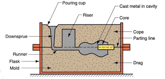
1. Sand Casting Process
Sand casting is a versatile casting process that can be used to cast any metal alloy, ferrous or non-ferrous. It is widely used for mass production in industrial units, such as automotive metal casting parts, like engine blocks, cylinder heads, crankshafts, etc.
The process uses a mold that’s made of silica-based materials, such as naturally-bonded or synthetic sand form the smooth mold surface. The mold surface has 2 parts, cope (the upper half) and drag (the lower half). Molten metal is poured into the pattern using a pouring cup and left to solidify to take the final shape. Finally, trimming off extra metal is done for the finishing of the final metal casting product.
Sand casting has its advantages and disadvantages.
Advantages
Disadvantages
Relatively inexpensive in terms of production costs, especially in low-volume production
Lower degree of accuracy as compared to alternate methods
Fabrication of large components
Difficult to use this method for products with pre-determined size and weight specifications
Casting both ferrous and non ferrous alloys
The process yields products with a rough surface finish
Recycling ability
Processing of metals with high melting temperatures, such as, steel and titanium
2. Gravity Die Casting
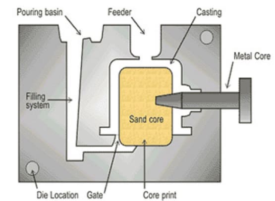
Gravity die casting, also typically known as permanent mold casting, uses reusable molds made of metal, like steel, graphite etc. to fabricate metal and metal alloys. This type of metal casting can manufacture various parts like gears, gear housing, pipe fittings, wheels, engine pistons, etc.
In this process, the direct pouring of molten metal into the mold cavity takes place under the effect of gravity. For better coverage, the die can be tilted to control the filling. The molten metal is then allowed to cool and solidifies within the mold to form products. As a result, this process makes casting of materials like lead, zinc, aluminum, and magnesium alloys, certain bronzes, and cast iron more common.
This casting process works on the bottom-up approach to fill the mold, in contrast, to other pressure casting processes. Although, the process has a higher casting rate than sand casting. But, it is relatively higher in cost due to expensive metal molds. Check its advantages and disadvantages below.
Advantages
Disadvantages
Provides better surface quality of products due to rapid solidification
Casting complex objects is difficult
Casting products have high precision and tight tolerance
Manufacturing costs of molds are higher
Reusable molds save time and increase productivity which reduces production costs
At times, the ejection mechanism to remove the casting from the mold forms a dent in the product
The products possess better mechanical properties
Production f thin walled products
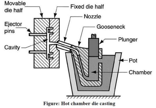
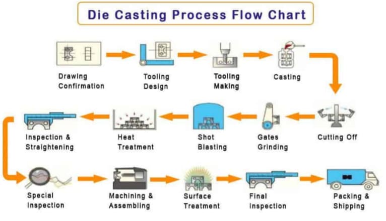
3. Pressure Die Casting
There are two types of pressure die casting depending on the pressure. Namely, the low-pressure die casting and the high-pressure die casting. High pressure die casting is more popular for mass production of complex geometries that require high precision. Whereas, for large and simple parts production, low-pressure die casting is a preferable casting process.
In this type of metal casting, non-ferrous metals and alloys such as zinc, tin, copper and aluminum are injected into a reusable mold coated with a lubricant at high pressure. Thus, high pressure is maintained throughout the rapid injection process to avoid metal hardening. Finally, after completion of the process, extraction of casting and finishing takes place to remove any excess material.
Pressure die casting differs from gravity die casting in the process of filling up the mold. Where pressure die casting uses high-pressure injection of molten metal into the metal mold. The molten metal is then solidified rapidly to produce the required product.
Its advantages and disadvantages are summarized below.
Advantages
Disadvantages
High precision and dimensional tolerance
Relatively high tool costs
High efficiency and good product quality
Limited to non-ferrous materials
Reduced need for post-casting machining
Difficult to ensure the mechanical properties of products, therefore, it is not used for structural parts
Rapid cooling of molten metal pertaining to faster production rates
Complete setup requires a large capital investment
The process can run for longer hours without the need to replace the die
More: Choose A Righ Process Between Die Casting vs Sand Casting for Your Applications.
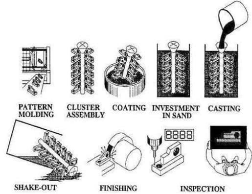
4. Investment Casting
Investment casting, also known as lost-wax casting, is a process that invests wax pattern with refractory material and a binding agent to shape a disposable ceramic mold, and then molten metal is poured into the mold to make metal castings. Investment casting is an expensive and labor-intensive process and can be used for mass production or in complex castings to produce metal casting products ranging from gears, bicycle trunks, moto discs, and spare parts in blasting machines.
Below summarizes its advantages and disadvantages.
Advantages
Disadvantages
It can produce parts with thin walls, more complexity and high surface quality
Requires labor for use
Reduces the need for post-casting machining
Production cycle is longer
Can cast hard-to-melt alloys such as stainless steel, thin steel, etc.
Higher manufacturing costs of molds
Due to breaking away of the shell mold, it allows for castings with 90-degree angles
New die requirement for the creation of wax patterns for each casting cycle
High dimensional accuracy in products
Shrinkage allowance in the mold
5. Plaster Casting
The plaster casting process is similar to sand casting, except that the mold is made of a mixture called ‘Plaster of Paris’. Due to the low thermal conductivity and heat capacity of plaster, it cools the metal more slowly as compared to sand, which helps in attaining high accuracy, especially for thin cross-section parts. However, it is not suitable for high-temperature ferrous materials.
Particularly, small castings of 30 grams, as well as large castings of 45 kilograms, can be manufactured through the plaster mold casting process. For example, the image below shows a cast component of a section thickness of 1 mm made by this process.
Learn more about its advantages and disadvantages.
Advantages
Disadvantages
Smooth surface finish
The process tends to be more expensive than most casting operations
Greater dimensional accuracy than sand casting
Limited applications to aluminum and copper-based alloys
The ability to cast complex shapes with thin walls
May require frequent replacements of the plaster molding material
Not suitable for high melting materials
Longer cooling times, effecting production rates
Unstable material as compared to sand, which can affect the complete process
6. Centrifugal Casting
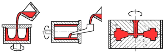
Centrifugal casting, also known as roto casting, is a process for industrially manufacturing cylindrical parts with centrifugal forces. This type of metal casting uses a preheated spinning die in which the molten metal is poured. The centrifugal forces help to distribute the molten metal within the die at high pressure.
Three variations of centrifugal casting exist; true centrifugal casting process, semi centrifugal casting process, and vertical centrifugal casting process. Semi centrifugal casting, unlike true centrifugal casting, has the mold completely filled using a sprue. However, in true centrifugal casting, molten metal sticks to the sides due to continuous rotation. On the contrary, vertical centrifugal casting, as the name suggests, uses directional molding following the same process as true centrifugal casting.
Typically, centrifugal casting produces rotational shapes like cylinders. In particular, parts like bush bearings, clutch plates, piston rings, and cylinder liners, etc. Also, the pouring of metal in the center of the mold helps in reducing defects such as blow holes, shrinkage, and gas pockets. However, it is not suitable for all kinds of metal alloys.
Advantages
Disadvantages
Improved process yields and reduced wastage
Centrifugal casting requires high investments
Casting has high density and almost no defects
Requirement of skilled labor
The process is convenient to manufacture barrel and sleeve composite metal castings
Specific shapes production
No requirement of gates and risers
7. Lost-Foam Casting
Lost-foam casting method is similar to investment casting with the difference that it uses foam for the pattern instead of wax. Once the pattern is formed, coating with a refractory ceramic takes place by dipping, coating, spraying, or brushing. Then, the molten metal is poured into the mold to form the desired product.
This technique can be used for various materials like alloy steel, carbon steel, alloy cast iron, ferrous alloy, etc. In particular, products like pump housing, fire hydrants, valves, and fittings are made through the lost-foam casting process.
Lost foam casting possesses numerous advantages which include high precision and high accuracy production. However, there are a few limitations of this process that makes it unsuitable for low-volume applications.
Advantages
Disadvantages
High precision casting
High pattern costs for low volume production
Allows flexible design
Low strength causes distortion or damage of the pattern
Clean production
Many production processes and longer delivery time
Economic for high volume production
8. Vacuum Casting
Vacuum casting, as the name suggests, is the type of casting where production occurs under vacuum pressure of 100 bar or less to exhaust gas from the mold cavity. In this process, molten metal is poured into the mold cavity inside a vacuum chamber in order to eliminate bubbles and air pockets. The vacuum evacuation of the die cavity reduces the entrapment of gases within the cavity during the metal injection process. Finally, the metal is cured in a heating chamber and removed from the mold.
The vacuum die casting process is popular in various industries including automobiles, aerospace, electronics, marine, telecommunication, etc. As a result, some components fabricated by this manufacturing process include structural chassis components and automotive body parts.
Advantages
Disadvantages
Reduce porosity, improve mechanical properties and surface quality of die casting
High tooling cost
Production of thin walled products
The mold used in the process has a short life
Welding and heat treatment of products is possible
Potential hollowness issues
Suitable for low volume production
No requirement for expensive hard tool finishing
Diminishes air pockets and bubbles at early stages
9. Squeezing Casting
Liquid forging or squeeze casting is a hybrid metal forming process that merges permanent mold casting and die forging in a single step. In this process, a specific amount of molten metal alloy is injected into a die, and pressure is applied to shape it. Then, the metal part is heated over melting temperature and extracted from the die.
Particularly, squeezing die casting is a potential casting process for safety-critical parts in automotive systems. For example, space frame joints, aluminum front steering knuckles, chassis frames, brackets, or nodes.
This type of metal casting combines the benefits of casting and forging processes. For example, the high pressure applied during solidification helps prevent shrinkage and porosities. However, due to specific tooling requirements, it is not as popular as other casting processes for mass production.
Advantages
Disadvantages
Eliminates internal defects like pores, shrinkage holes and shrinkage porosity
Less flexibility in part geometry
Low surface roughness
Lower productivity
It can prevent casting cracks
High machining requirements
High strength components
Requires accurate controlling, slowing down the overall process
No wastage of material
10. Continuous Casting
As the name suggests, it allows consistent mass production of metal profiles with a constant cross-section. This type of casting is popular in the production of steel bars. Also, the vertical cast creates semi-continuous casting like billets, ingots, bars, etc.
In this process, molten metal is poured at a calculated rate in a water-cooled, open-ended mold that allows a surface of solid metal to form on the liquid metal in the center. Metal solidification, thus, happens from the outside in. After this process finishes, strands of metal can be continuously extracted from the mold. Predetermined lengths of products can be cut off by mechanical shears or traveling oxyacetylene torches.
Generally, the products created using continuous casting are homogeneous, consistent, and dense. However, it also limits its use to such applications. Some other advantages and disadvantages are:
Advantages
Disadvantages
Diverse size range of casting products varying from a few millimeters thick strip to larger billets and slabs
Requirement of continuous cooling of the molds, otherwise, center-line shrinkage develops
Lower costs due to continuous production
Casting of only simple shapes with a constant cross-section
Lower material wastage
Requires large ground space and high initial investment
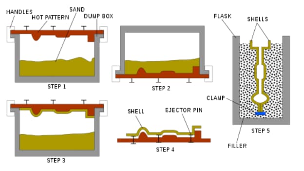
11. Shell Molding
Shell molding is an expendable mold casting process. It is similar to the sand casting process except for that the hardened shell of sand forms the mold cavity instead of a flask of sand. The sand used is finer than that utilized in sand casting and it is mixed with a resin so that it can be heat treated and hardened into the shell around the pattern.
Shell molding makes industrial products, for example, gearbox housing, connecting rod, small-size boats, truck hoods, cylindrical heads, camshafts, valve bodies, etc.
The casting products possess a good surface finish and dimensional accuracy. However, the limitation of this kind of casting includes the size and weight limitation of the parts. Some other advantages and disadvantages are:
Advantages
Disadvantages
Casting of thin and complex parts
Not suitable for small scale production
Semi-skilled labor
Limitations on size and weight
No further machining required
Special metal pattern required which makes it expensive for large casting
Accounts for surface defects
Basic Steps of Different Casting Production
Mostly, casting processes follow some basic steps like pattern making, mold making, selection and pouring of metal alloys and finally, finishing of the casted part.
Pattern making
To create a pattern, it is important to determine the shape of the mold. For this, the materials used are wax, sand, plastic or even wood.
Mold making
Following on, there is a requirement to create different types of molds for casting. Single-use mold can be made out of sand, plaster, or ceramic shell. Each of them has a different production method. Also, patterns made from foam or wax are burnt in a kiln.
Choose metal alloys
Metal castings are produced from ferrous or non-ferrous alloys. Alloys are a chemical mixture of elements with mechanical properties which are best for the final cast applications. Where, ferrous alloys include steel, malleable iron and gray iron. While non-ferrous metals include aluminum alloys, bronze and copper.
Melt and pour the alloy
After the selection of the metal alloys, the next step is the pouring of metal into the mold. The process involves placing a solid metal over a crucible and heating it with an open flame or inside the furnace until it melts. For small casting, pouring the molten metal directly from the crucible is possible. However, larger castings may require the transferring of metal into a larger ladle before pouring into the mold.
Finishing
After solidification, the casting product is removed and metal surface finishing is done on it. Furthermore, the process of finishing can include the removal of excess material by scrubbing or machining for larger waste material.
Outsource Your Casting Needs to RapidDirect
It is important to choose the right type of casting process and expertise for your products. At RapidDirect, we provide you access to a team of professional engineers with a vast experience in different casting services, like die casting services, vacuum casting, etc. The expertise of our working team puts us in a better place to advise you and answer any queries that you may have.
We provide rapid online quotes for your parts on uploading a design file to our online quotation platform. You can rest assured that we provide the best at competitive market pricing.
CNC machining is one of the core processes in manufacturing that produce intricate and sophisticated products that have applications in various industries. At the heart of CNC machining’s unmatched efficiency and accuracy are the G and M codes – the critical programming languages that guide CNC machines.
Unlike common perception, G codes and M codes hold distinct roles in CNC operations. G codes primarily instruct the machine on the geometry of the cut, while M codes control the hardware aspects, like turning the spindle on or off. This nuanced difference is pivotal for understanding the full potential of CNC machining.
In this article, we delve into the specifics of these codes, unraveling their unique functions and how they synergize to optimize CNC machine performance.
What’s CNC Machining?
Understanding CNC machining is fundamental before delving into the specifics of CNC programming codes. CNC machining, or Computer Numerical Control machining, utilizes computerized controls and machine tools to produce precise and intricate parts from various materials. The technology has significantly transformed the landscape of modern manufacturing as it offers increased efficiency, and accuracy, and can create complex geometries.
Its key advantages are:
Precision: CNC machining offers high precision and accuracy in producing complex parts.
Efficiency: Automated processes and optimized tool paths contribute to efficient material removal.
Versatility: Suitable for a wide range of materials and applications.
Repeatability: CNC machines can produce identical parts with consistent quality.
How Does CNC Programming Control CNC Machines?
Before the advent of computers, machinists used cards or tapes to control machine movements. They punched holes in these cards in a specific order to create the codes. While this was also effective at the time, it was quite tedious. Also, these cards were prone to damage or getting lost in the machine shops. This led to several problems in production at the time.
When machinists started using computers for numerically controlled machines, they still came across a few problems. This was because they had to input the codes manually. This would, of course, be very tedious when they were making quite sophisticated parts that required a lot of instructions.
The advent of advanced computers and software has revolutionized CNC machining. Machinists now simply input instructions into software, which then generates the necessary G codes and M codes for the machines. This process, greatly simplified by CAD and CAM software, has made code generation and machine operation more efficient and accessible, enhancing both precision and complexity in manufacturing.
To start the process, the programmer needs high-level computer-aided software. The programmer then imports the machine model and the machining fixture into the software, then selects the tools and the tooling paths of the spindle. Once these parameters are set, the software efficiently generates the requisite G and M codes, which are essential for the CNC machine to operate effectively.
What Are G-Codes in CNC Programming?
G code (also RS-274D) is the most popular CNC programming language. Most G code commands are in alphanumericformat and start with G which stands for geometry. They are responsible for the movements of CNC machines, telling the machine where to start, how to move, and when to stop when fabricating a part.
However, G code can be quite complicated for machinists because different machines read G codes in different formats. Most machines’ differences are in the presence or absence of spaces between commands and the number of zeros between the letter and number in the commands. For example, a machine might use G3 while another uses G03. Machinists must always be conversant with the type of machine they’re using. Otherwise, errors in the command can lead to serious problems in parts production.
Beyond G codes, programmers use other letters that signify distinct functions as well. These letters diversify the language of CNC programming, enabling a wide range of commands for precise and intricate machining tasks.
A: It directs the tool around the x-axis.
R: It gives the radius of the arcs the machine makes.
X, Y, Z: These three values indicate the tools’ position in three dimensions – X and Y represent the horizontal and vertical dimensions, respectively, while Z represents the depth.
I and J: Both values designate the incremental center of any arc the machine makes.
N: N gives the line number.
The code also uses other letters which depend on the machine’s capabilities.
Block
Description
Purpose
%
Start of program
Start Program
O00001 (Project 1)
Program number (Program Name)
Start Program
(T1 0.25 END MILL)
Tool description for operator
Start Program
N1 G17 G20 G40 G49 G80 G90
Safety block to ensure the machine is in safe mode
Start Program
N2 T1 M6
Load Tool #1
Change Tool
N3 S9200 M3
Spindle Speed 9200 RPM, On CW
Change Tool
N4 G54
Use fixture Offset #1
Move to Position
N5 M8
Coolant on
Move to Position
N6 GOO X-0.025 Y-0.275
Rapid above part
Move to Position
N7 G43 Z1. H1
Rapid to the safe plane, use tool length Offset #1
Move to Position
N8 ZO.1
Rapid to feed plane
Move to Position
N9 G01 Z-0.1 F18
Line move to cutting depth at 18 IPM
Move to Position
N10 G41 Y0.1 D1 F36
CDC left Lead in Line, Dia. Offset #1, 36 IPM
Machine Contour
N11 Y2.025
Line Move
Machine Contour
N12 X2.025
Line Move
Machine Contour
N13 Y-0.025
Line Move
Machine Contour
N14 X-0.025
Line Move
Machine Contour
N15 G40 X-0.4
Turn CDC off with lead-out move
Machine Contour
N16 G00 Z1
Rapid to safe plane
Machine Contour
N17 MS
Spindle Off
Change Tool
N18 M9
Coolant Off
Change Tool
(T2 0.25 DRILL)
Tool description for operator
Change Tool
N19 T2 M6
Load Tool #2
Change Tool
N20 S3820 M3
Spindle Speed 3820 RPM, On CW
Change Tool
N21 M8
Coolant On
Move to Position
N22 X1 Y1
Rapid above hole
Move to Position
N23 G43 Z1 H2
Rapid to safe plane, use tool length, Offset 2
Move to Position
N24 Z0.25
Rapid to feed plane
Move to Position
N25 G98 G81 Z-0.325 RO.1 F12
Drill hole (canned) cycle. Depth Z-.325, F12
Drill Hole
N26 G80
Cancel drill cycle
Drill Hole
N27 Z1
Rapid to safe plane
Drill Hole
N28 MS
Spindle Off
End Program
N29 M9
Coolant Off
End Program
N30 G91 G28 Z0
Return to Machine Home Position in Z
End Program
N31 G91 G28 X0 Y0
Return to Machine Home Position in XY
End Program
N32 G90
Reset to absolute positioning mode (for safety)
End Program
N33 M30
Reset the program to the beginning
End Program
%
End Program
End Program
What Are M-Codes in CNC Programming?
M code, akin to G code, commences with the letter ‘M’ and encompasses a series of auxiliary commands vital for controlling a CNC machine’s non-geometric functions. These codes, often referred to as miscellaneous codes, manage essential operations like halting the program, activating coolant systems, and powering down the machine post-operation.
In CNC programming, it is crucial to use M codes with precision. Typically, each block of program information should contain only one M code. This practice is imperative because M codes often serve to activate or deactivate various machine functions. Overlapping these commands within a single block can lead to programming conflicts and operational errors.
Similar to G codes, M codes vary across different CNC machines. This variance can include differences in the numerical formatting of the codes, such as the inclusion or exclusion of leading zeros. For instance, one machine might recognize an M code as ‘M3’, while another requires ‘M03’. Therefore, machinists must be well-versed in the specific coding requirements of the equipment they operate to ensure seamless and error-free machining processes.
A List of G and M Codes for CNC Machining
This section illustrates a range of basic G and M codes, highlighting their distinct functionalities. While some codes have similar meanings across both lists, others differ significantly in application and interpretation in CNC machining.
Commonly Used of G Codes
G-codes in CNC machining transform complex operations into methodical tasks, with standardized codes ensuring consistency and peak performance. Here’s a look at some key G-Codes crucial for anyone working with CNC machines.
G00 – Rapid Positioning: This command is used for swiftly moving the tool to specified coordinates at maximum speed. Primarily, it positions the tool without engaging in material cutting, optimizing the machine’s efficiency for non-cutting movements.
G01 – Linear Interpolation: This command directs the tool to move in a straight line between two points at a set feed rate. Predominantly utilized for straight-line cutting, G01 is one of the most frequently used G codes in CNC machining.
G02 – Circular Interpolation (Clockwise): This command facilitates the creation of arcs and circles by guiding the tool along a circular path in a clockwise direction. It ensures precise movement to a specified endpoint, essential for circular machining tasks.
G03 – Circular Interpolation (Counter-Clockwise): This command mirrors G02, but with the tool moving along a circular path in a counter-clockwise direction. It’s essential for crafting arcs and circles that require a counter-clockwise approach.
G04 – Dwell: This command instructs the CNC machine to temporarily pause at its current position for a predefined period. The dwell function is particularly useful in scenarios such as allowing a cutting tool to cool down or enabling the spindle to attain the desired speed.
A List of Other Function G Codes
Code
Category
Function
Modal
For Turning or Milling
G17
Plane Selection
XY Plane Selection
Yes
Both
G96
Speeds and Feeds
Constant Surface Speed
Yes
Turning
G91
Positioning and Modes
Incremental Mode
Yes
Both
G03
Circular Interpolation (CCW)
Create arcs and circles (Counter-Clockwise)
Yes
Both
G04
Dwell
Pause for a specified duration
No
Both
G18
Plane Selection
XZ Plane Selection
Yes
Turning
G19
Plane Selection
YZ Plane Selection
Yes
Turning
G20
Unit System
Inch System
Yes
Both
G21
Unit System
Metric System
Yes
Both
G40
Cutter Compensation
Cancel Cutter Compensation
Yes
Milling
For additional information on G codes, please refer to this resource.
Commonly Used M Codes
Although CNC machines typically use M-codes akin to G-codes, standardization across models isn’t universally adopted. Thus, CNC programmers must be cautious about machine-specific codes. Yet, certain M-codes consistently retain the same meaning across all machines.
M00 – Program Stop: To stop the CNC program temporarily. It often requires operator intervention to resume the program.
M02 – Program End: To end the CNC program. After executing this code, the control will stop, and the operator may need to reset or restart the machine.
M03 – Spindle On, clockwise: To start the spindle rotation in the clockwise direction. It is often followed by a speed command (S) to set the spindle speed.
M04 – Spindle On, Counterclockwise: Similar to M03, M04 is used to start the spindle, but it rotates in the counterclockwise direction.
M05 – Spindle Stop: To stop the spindle rotation. It is often employed when a tool change or other operation requires the spindle to be stationary.
A List of Other Function M Codes
Code
Category
Function
Modal
For Turning or Milling
M08
Coolant
Coolant flood or on
No
Both
M42
Auxiliary Functions
High Gear Select
No
Turning
M19
Spindle Control
Change spindle orientations
No
Milling
M00
Program Control
Program Stop
No
Both
M02
Program Control
Program End
No
Both
M03
Spindle Control
Spindle On, Clockwise
No
Both
M04
Spindle Control
Spindle On, Counterclockwise
No
Both
M05
Spindle Control
Spindle Stop
No
Both
M06
Tool Change
Tool Change
No
Both
M09
Coolant
Coolant Off
No
Both
For additional information on M codes, please refer to this resource.
Let’s Summarize The Difference Between G and M Codes
G-codes:
Direct the motion and function of the CNC machine.
Describe positions and movements, such as rapid positioning to a specific XY plane, linear feed movement, and circular interpolation.
Related to geometric codes, serve in product design.
Activate the CNC machine.
M-codes:
Control operations not involving movements, such as stopping programs, changing tools, turning the spindle on or off, and activating coolant systems.
Relate to machine functions and serve in various miscellaneous operations.
Activate the machine’s programmable logic controller (PLC).
RapidDirect’s Expertise in CNC Machining
Explore CNC machining solutions with RapidDirect, where understanding and precision meet. Our team is skilled in the intricacies of G and M codes, ensuring that every project is handled with attention to detail and expertise. We believe in offering high-quality results that are both effective and affordable.
Our user-friendly platform streamlines your experience, offering instant quotations and a straightforward project tracking process. Managing your CNC machining needs becomes effortless with our efficient and accessible system.
You switched to Nano Banana for its precise context-aware editing, only to hit hard limits when you need consistent product visuals or 3D assets for manufacturing. Many alternatives promise similar editing power, but few deliver the reliability commercial teams need for e-commerce, prototyping, and production. The right tool cuts weeks from your content pipeline while ensuring your designs can move seamlessly from screen to physical product.Today, we’re reviewing 7 Nano Banana alternatives, all of which were tested and proven effective by product teams and e-commerce sellers in 2026. Each has a clearly defined best-use scenario, so you’ll be able to find the one that suits you best after reading this review.
Top Nano Banana Alternatives Comparison (2026)
Tool Name
Best For
Core Output
Image Quality
3D Capability
Export Formats
Pricing
RapidDirect AI Creator
Product teams & end-to-end manufacturing
Product visuals, production-ready 3D models
9/10
9/10
PNG, JPG, GLB, STL
Free
Flux Kontext
Context-aware local editing (closest to Nano Banana)
RapidDirect AI Creator – Best for Product Teams That Need to Manufacture
RapidDirect AI Creator is not a generic ai image generator. It is built exclusively for product teams that need to move from concept to physical production. Unlike Nano Banana and other pure editing tools, it prioritizes product accuracy, multi-angle consistency, and direct integration with manufacturing workflows.
You can generate consistent product visuals from simple text prompts, then convert your favorite 2D renders into production-ready 3D models with one click. All outputs are optimized for downstream engineering, eliminating the need to rebuild models from scratch when you move to prototyping.
Key Specs:
Output type: Product-focused 2D renders, manufacturing-ready 3D models
Flux Kontext – Best for Context-Aware Local Editing
Flux Kontext is the best nano banana alternative for teams that rely heavily on precise local editing. Its context preservation technology matches and in many cases exceeds Nano Banana’s ability to modify specific parts of an image without breaking the overall scene.
The tool excels at product retouching, background replacement, and style transfers while maintaining consistent lighting and perspective. It supports multiple reference images and can apply changes across entire batches of product photos. Flux Kontext is primarily accessed via API, making it ideal for teams building automated content pipelines.
Editability: Pixel-perfect local editing with full context preservation
Export formats: PNG, JPG, layered PSD
Commercial usage: Full rights for paid API users
Batch support: High-volume batch processing via API
Integration: REST API, Zapier, and popular design tools
Price tier: Pay-as-you-go API pricing from $0.02 per generation
Pros:
Most accurate context-aware editing on the market
Excellent at preserving product details and lighting
Robust API for automation
Supports unlimited reference images
No content restrictions for commercial use
Cons:
No native 3D generation capabilities
No direct path to manufacturing
Higher cost for high-volume usage
Limited web interface; best for technical teams
DALL-E 3 – Best for Accurate Prompt Following & Text Rendering
DALL-E 3 remains the gold standard for prompt adherence and text rendering among free ai image generator options. It reliably follows complex, detailed instructions and produces legible, properly formatted text on product labels, packaging, and marketing materials.
The tool integrates seamlessly with ChatGPT, allowing you to refine prompts iteratively in natural language. It works best for teams that need to generate quick product concepts, packaging mockups, and marketing visuals. DALL-E 3’s strict content policies make it unsuitable for some niche product categories.
Key Specs:
Output type: Text-to-image, image-to-image edits
Editability: Generative fill and basic modifications
Seedream 4.0 – Best for Commercial 4K Product Photography
Seedream 4.0 produces the most photorealistic product visuals of any ai image generator available in 2026. Its native 4K output requires no upscaling, and it accurately reproduces complex materials like brushed metal, glass, and soft fabrics.
The tool is widely used by top DTC brands and e-commerce agencies for main product images, lifestyle shots, and advertising visuals. It offers advanced controls for lighting, camera angles, and background environments. Seedream 4.0’s enterprise-only pricing makes it best for mid-sized and large teams with significant content needs.
Dedicated account management for enterprise clients
Advanced studio lighting controls
Cons:
No self-service entry-level plans
No 3D generation capabilities
No direct manufacturing integration
Higher cost per image than most alternatives
Magic Hour – Best for All-in-One Image + Video with High Free Credits
Magic Hour is the best free nano banana alternative for teams on a budget. It offers 400 initial credits plus 100 permanent daily credits, with no expiration on unused points. The platform combines image generation, editing, and video creation in a single interface.
Its editing capabilities are solid for most commercial use cases, including background removal, generative fill, and style transfers. Magic Hour also supports basic text-to-video generation, making it a good choice for teams that need both product images and short social media clips.
Commercial usage: Full rights for paid tiers; free tier requires attribution
Batch support: Basic batch generation
Integration: API access on all plans
Price tier: $10/month (Creator); free tier with watermark and attribution
Pros:
Generous permanent free credit allocation
All-in-one image and video workflow
Intuitive user interface
API access on all plans
Credits never expire
Cons:
Free tier includes watermarks and requires attribution
Maximum 576px resolution on free tier
Product realism lags behind Seedream 4.0
No 3D generation or manufacturing support
Midjourney – Best for Artistic & Cinematic Visual Creation
Midjourney produces the most visually striking artistic and cinematic output of any tool in this roundup. Its lighting, composition, and color grading are unmatched for concept art, lifestyle imagery, and brand storytelling.
The tool works best for early-stage creative exploration and marketing visuals that prioritize emotional impact over technical accuracy. Midjourney’s Discord-only interface and limited editing capabilities make it less suitable for precise product retouching or iterative design work.
Qwen Image – Best for Open-Source Self-Hosting & Full Privacy
Qwen Image is the only fully open-source nano banana alternative on this list. It is released under the Apache 2.0 license, allowing complete customization, self-hosting, and unrestricted commercial usage with no fees.
The tool delivers solid performance for most general-purpose image generation and editing tasks. It has particularly strong text rendering capabilities, comparable to DALL-E 3. Self-hosting requires GPU resources, making it best for teams with technical expertise and strict data privacy requirements.
Key Specs:
Output type: General-purpose images and edits
Editability: Generative fill and basic modifications
Export formats: All common image formats
Commercial usage: Completely unrestricted
Batch support: Unlimited via self-hosted deployment
Integration: Full API access and custom integration
Price tier: Free (self-hosted); third-party hosting options available
Pros:
100% free and open-source
No usage restrictions or content policies
Full data privacy and control
Strong text rendering capabilities
Customizable and fine-tunable
Cons:
Requires technical expertise to self-host
No official technical support
Product realism lags behind commercial tools
No 3D generation or manufacturing support
Less polished user interface
Final Recommendations
The best nano banana alternative depends on your specific workflow and end goals. For product teams that need to move from concept to manufacturing, RapidDirect AI Creator is the clear choice. It is the only tool that bridges the gap between AI design and physical production.
For teams that primarily need precise 2D editing capabilities, Flux Kontext offers the closest match to Nano Banana’s core functionality. Magic Hour provides the best value for budget-conscious teams, while Seedream 4.0 delivers the highest quality commercial product visuals.
Remember that AI visuals are a starting point, not a final product. The most successful teams use AI to explore more design options faster, then work with experienced engineers to turn those concepts into real, manufacturable products.
FAQs about nano banana alternative
What is the closest alternative to Nano Banana’s context-aware editing?
Flux Kontext is the most accurate replacement for Nano Banana’s core editing functionality. It matches and in many cases exceeds Nano Banana’s ability to perform local edits while preserving full scene context and lighting.
Are there any completely free Nano Banana alternatives?
Qwen Image is 100% free and open-source with no usage restrictions. Magic Hour offers 400 initial credits plus 100 permanent daily credits for free, though the free tier includes watermarks and requires attribution.
Can AI-generated product images be used commercially?
All paid tools in this guide grant full commercial usage rights for generated content. Free tiers often have restrictions, including watermarks, attribution requirements, or limits on commercial usage. Always verify the specific licensing terms before using AI-generated content for commercial purposes.
What is the core difference between Nano Banana and RapidDirect AI Creator?
Nano Banana is a pure image editing tool focused on 2D content. RapidDirect AI Creator is a product development tool that generates both 2D visuals and 3D models, with direct integration to manufacturing services. It is built for teams that need to build real products, not just create images.
Wondering aboutCNC machining and why it’s a big deal in the manufacturing world? You’re not alone. Computer Numeric Control (CNC) Machining is a key player in modern manufacturing, using advanced technology to cut, shape, and create parts with precision.
This article breaks down the basics of how CNC machines work and their role in making everything from car parts to tech gadgets. We’ll also look at the many industries that rely on this technology and why it’s so important.
Overview of CNC Machining
CNC machining, controlled by computers, produces high-precision parts and components. In this process, a computer program controls the movement of the cutting tools, which the CNC programming controls to remove material from a workpiece to create a finished part.
CNC technology produces an array of parts and components, including those made from metal, plastic, and other materials. The process can also produce parts with complex geometries and high levels of precision, making it a popular choice for applications in numerous industries, including aerospace, automotive, medical devices, and consumer products.
It offers several advantages over traditional machining methods, including improved accuracy, consistency, and speed, as well as the ability to produce complex geometries and intricate details. It also allows for the use of advanced cutting tools and techniques, such as multi-axis machining centers and high-speed machining, which can further improve the efficiency and quality of the process.
The History of CNC Machining
Its history can be traced back to the 1940s when the first numerical control (NC) machines were developed. Over time, these machines became more widespread and sophisticated. This gave them the capability to fulfill the requirements of a variety of industries including aerospace, automotive, and defense.
However, older NC machines still needed manual input and had limited capabilities.
The transformation of manufacturing began in the 1970s with the introduction of computers, leading to a breakthrough: the first CNC machines. These advanced machines, equipped with computer controls, could process data with unprecedented speed and accuracy. This innovation allowed CNC operators to input commands directly into the machine, which then automatically executed the necessary operations, significantly streamlining the manufacturing process.
This was only the beginning of CNC machines as the technology continued to advance over the years. The development of more advanced software and hardware along with the introduction of new material and tooling options meant more possibilities for manufacturing units.
Today, CNC machinery is common in multiple industries and is capable of producing a diverse range of products with high levels of accuracy and precision.
How CNC Machining Works?
Contemporary CNC systems focus on minimizing human intervention as much as possible. This ensures consistent and continuous performance, which facilitates smart manufacturing and delivers excellent results.
However, CNC manufacturing requires careful consideration from the initial design to the final manufacturing. The entire process works in three different steps:
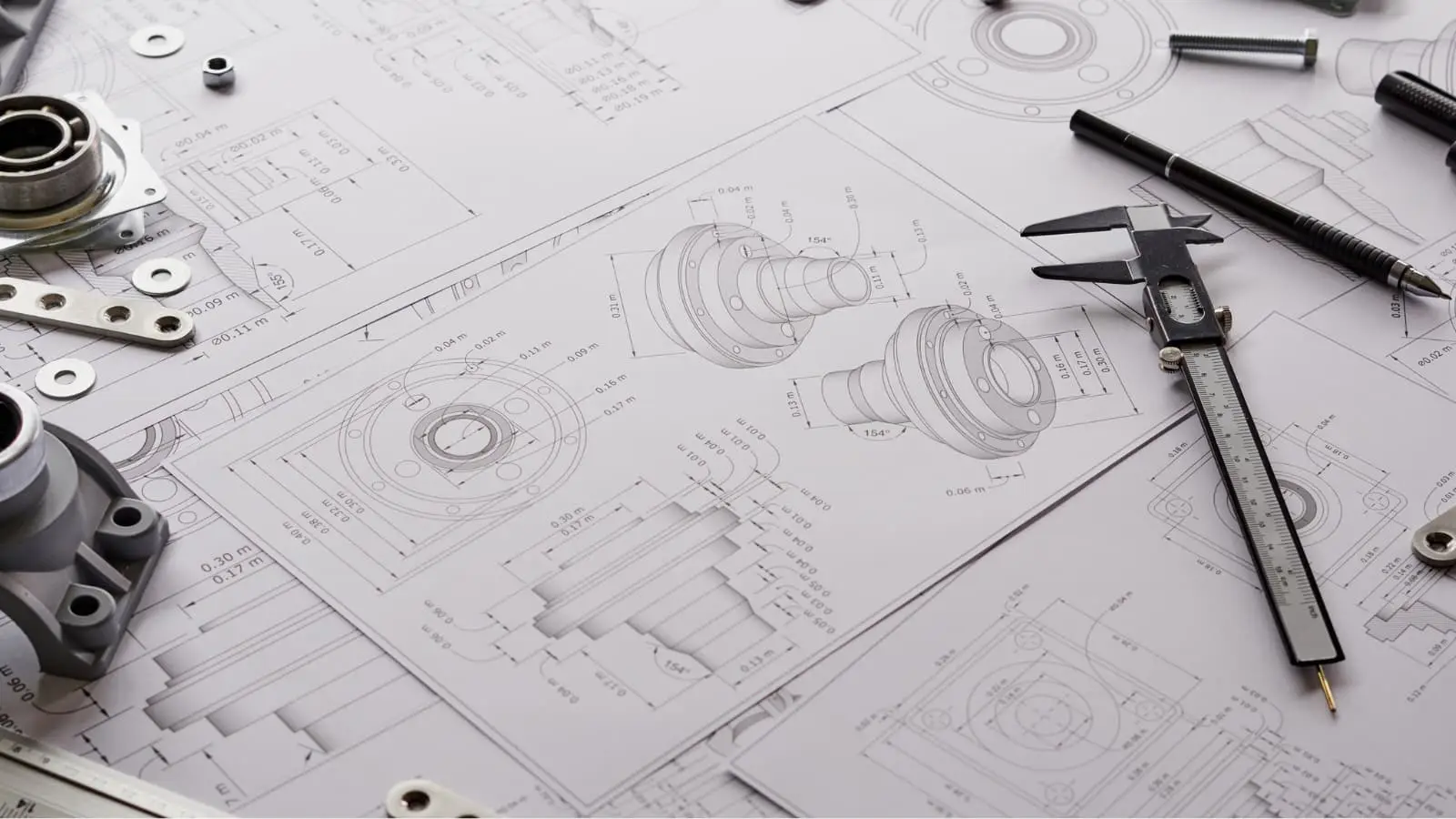
1 – Design
The first crucial step in CNC machining involves software applications like CAD, CAM, and CAE. Engineers and designers rely on these tools to design parts and products, and then assess their manufacturability. This assessment, known as Design for Manufacturing (DFM), is vital. It ensures that the design is optimized to maximize efficiency and reduce costs, all while working within the constraints of existing technology.
In most cases, the CAD tools available in the market come with an internal CAM tool, which facilitates the pre-processing and programming.
After finalizing the CAD design, the designer converts it into a CNC-compatible file format, typically STEP or IGES.
2 – Pre-processing and Programming
CNC machine programming primarily involves using G-codes and M-codes to communicate with machines. These codes, generated by CAM packages, act as a guide for the cutting tool’s path in CNC operations.
Usually, if a design adheres to DFM (Design for Manufacturing) standards, CNC machinists don’t need to intervene in the pre-processing or operational stages. However, if the design doesn’t meet these standards, some level of manual intervention may be required to guarantee optimal performance.
Pre-processing is a standard step in CNC machining, and its duration depends on the design’s quality. Programming the G-Codes or M-Codes typically takes just a few minutes. However, the success of CNC programming hinges on the design’s adherence to DFM conventions. Accurate designs produce correct codes and satisfactory results, while design flaws lead to erroneous codes and poor outcomes.
3 – Machining
The final stage is the machining process, which uses the provided codes from the previous step to remove excess material from a block.
Precision in machine tooling is crucial, yet it’s often challenging to replicate the exact dimensions of a CAD model. This is why machinists typically apply standard ISO 2768 tolerances, which vary based on industry requirements. It’s a widely accepted principle that tighter tolerances lead to increased manufacturing costs.
Common CNC Operations Across the Industry
CNC machining is a versatile process with operations varying based on specific requirements. Simple designs might be achieved through a single operation, such as milling. However, more complex designs typically require a greater variety of operations.
Below are some key CNC machining equipment widely used in the industry.
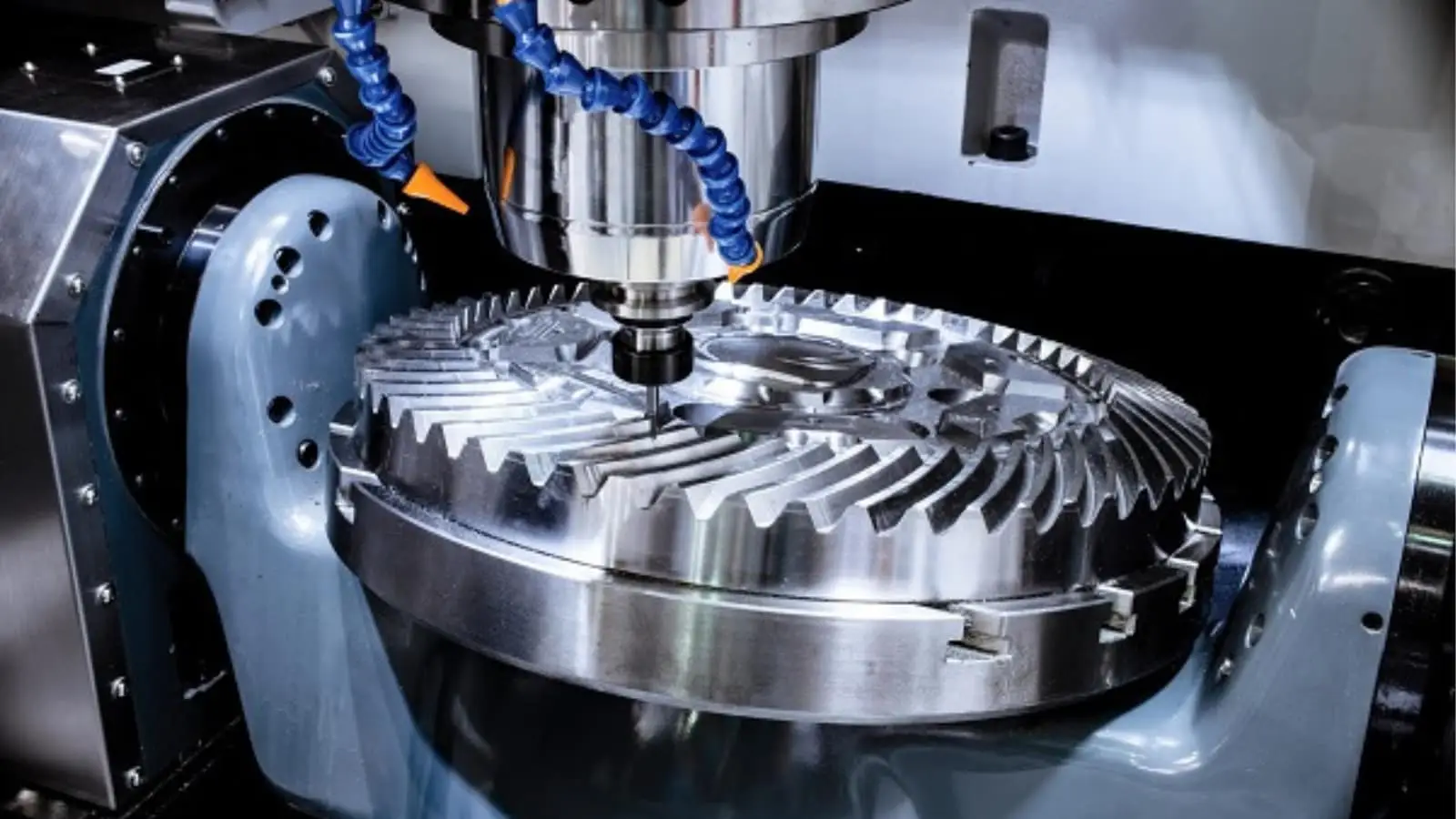
CNC Milling
CNC milling is a highly precise and versatile machining process used to remove material from a solid block to create a specific shape or design. It involves the use of a CNC system to manipulate a multi-point cutting tool, typically a milling cutter, with extreme accuracy. During this process, the workpiece is securely mounted on a table, and the milling cutter is rotated at high speeds to systematically chip away at the material. This method is particularly effective for generating flat surfaces, but its capabilities extend far beyond simple shapes.
One of the key features of CNC mills is their ability to perform intermittent cutting with multiple machine steps, allowing for the efficient creation of complex geometries. The technology has evolved to include 3, 4, and 5-axis milling machines:
3-Axis Milling: Movements along the X, Y, and Z axes enable basic operations like drilling and planning. Ideal for straightforward projects requiring simple shapes, this method is popular for its simplicity. However, it’s limited in creating complex geometries, making it best suited for less intricate designs.
4-Axis Milling: Adding a rotational axis, allows for more complex operations than 3-axis milling. This method is ideal for angular cuts and more intricate shapes, expanding the capabilities of CNC machining. It’s particularly useful for parts requiring additional precision that 3-axis milling machines can’t provide.
5-Axis Milling: The pinnacle of CNC milling, this type of machining method moves along five axes simultaneously, allowing for extreme precision and complexity. It’s invaluable in high-precision industries for creating complex shapes with tight tolerances. This method streamlines production by reducing the need for multiple setups, ensuring efficiency and accuracy.
CNC Turning
CNC turning is a highly efficient machining process predominantly used for shaping cylindrical workpieces, although it can also handle square or hexagonal-shaped raw materials. At its core, CNC turning involves the use of a computer-controlled lathe that rotates the workpiece against various cutting tools. These tools trim and shape the material into the desired cylindrical form.
The uniqueness of the turning machine lies in its versatility and precision, governed by different spindles and speed capabilities. This process can be performed on both vertical and horizontal setups, each catering to specific types of workpieces and machining requirements.
There are two main types of machines:
CNC Lathes: It excels in precision turning operations, ideal for crafting cylindrical parts with high accuracy. It operates by rotating the workpiece against a stationary tool, making it perfect for simple to moderately complex shapes, commonly used in automotive and aerospace industries.
CNC Turning Centers: It combines turning with additional functions like milling and drilling. This multi-tasking capability allows for producing complex parts in a single setup, enhancing efficiency and accuracy. It’s essential in industries requiring intricate, multifaceted components, such as advanced manufacturing.
CNC Drilling
Drilling is an important manufacturing process that creates different-sized thread holes in a workpiece. The process is completely automated because of the involvement of a computer that precisely controls the movement and speed of the drill bit.
CNC drilling is quite common in many industries including printed circuit boards, metal parts, and plastics. The process offers several advantages over traditional manual drilling, including increased accuracy, repeatability, and efficiency.
CNC Routing
The crude operations of CNC routers are the same as milling machines. Routers generally deal with softer materials like wood while milling is common for tougher metals. Just like any CNC operation, routers also deliver excellent consistency, efficiency, and accuracy.
In the routing process, the workpiece remains completely stationary while the spindle moves in different directions. Since the routing process is for softer materials, the overall rotating speed of the spindle can be quite low. There are numerous CNC routing machines, including benchtop routers, gantry routers, and moving gantry routers. The choice of machine and cutting tool will depend on the specific requirements of the workpiece and the desired end product.
Electric Discharge Machining
An electric discharge machine (EDM) is a manufacturing process that utilizes electrical spark discharges to erode material and produce complex shapes and geometries.
The process works by creating a spark between an electrode and the workpiece. The machinists submerge the workpiece in a dielectric fluid, which isolates the electrical energy and allows for the precise control of the spark. The spark discharge vaporizes the workpiece and removes access material to obtain the required shape.
There are two main EDM types: sinker EDM and wire EDM. Sinker EDM uses a consumable electrode to create the spark. Contrarily, wire EDM uses a thin wire that moves to and fro to create the spark.
CNC Plasma Cutting
CNC plasma cutting is a dynamic manufacturing process widely used in large-scale industrial settings, renowned for its ability to make high-speed and precise cuts in electronically conductive materials like steel, stainless steel, aluminum, brass, and copper. This method involves a plasma torch that creates a powerful plasma arc between an electrode and the workpiece, effectively melting and vaporizing the material at the point of contact. A critical component of this process is the high-pressure stream of gas, such as air or nitrogen, which expels the molten material from the cut area, resulting in a clean, precise edge with minimal deformation or discoloration.
This technique stands out for its versatility, seamlessly cutting both thin and thick materials, which broadens its industrial applications. Moreover, plasma cutting is cost-effective, offering lower operational costs compared to other methods. Its integration of speed, precision, and affordability makes it an essential tool in modern manufacturing, particularly in industries where efficiency and accuracy are crucial.
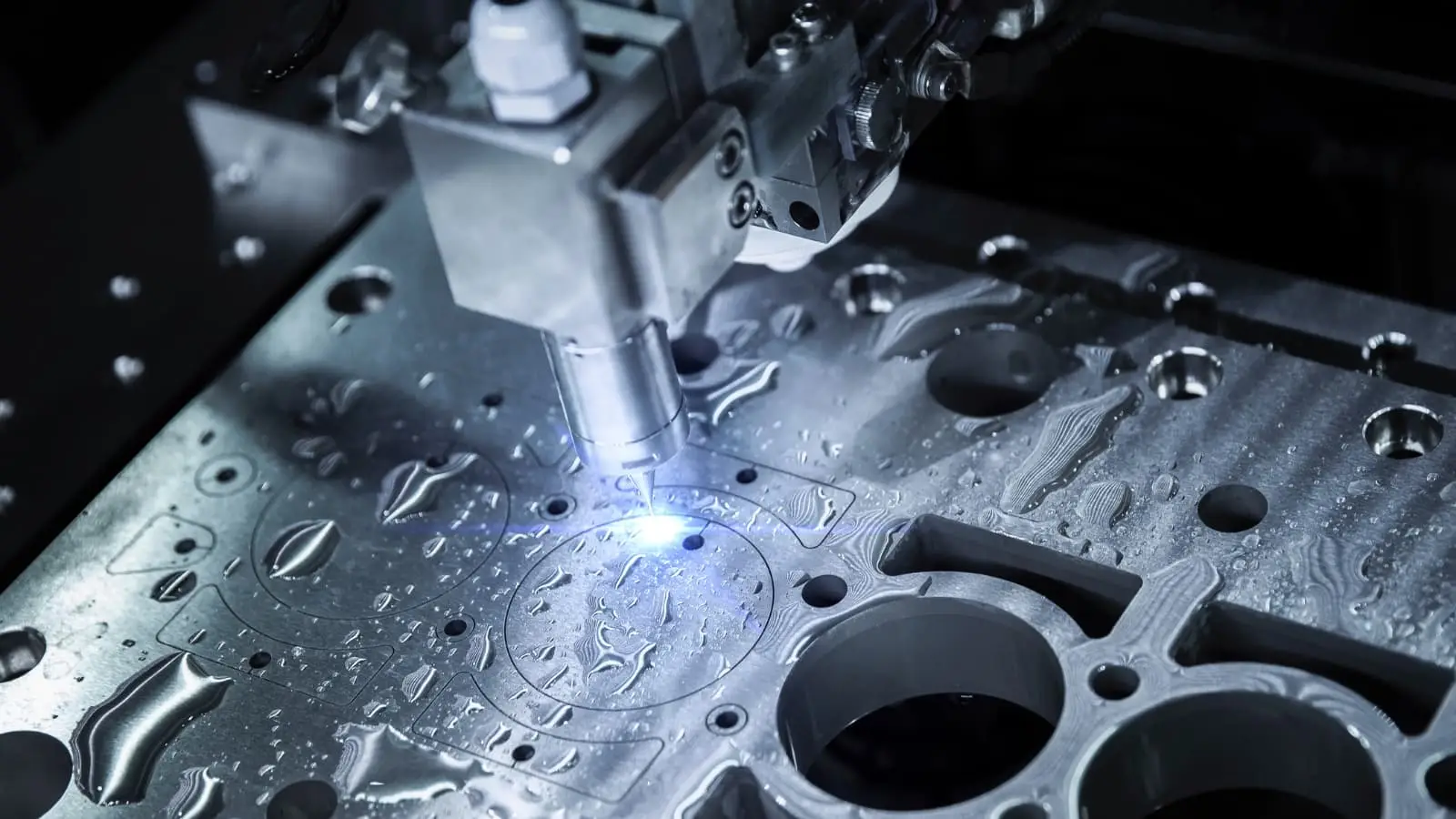
CNC Laser Cutting
CNC laser cutting, a staple in industrial manufacturing, is celebrated for its precision and speed. It employs advanced lasers, including CO2, Nd, and Nd: YAG types, to effectively vaporize materials, ensuring clean and precise cuts. This technology is versatile enough to handle a wide range of materials, contributing to its widespread use across various industries.
The technology’s precision is not just limited to single operations; it excels in repeatability, which is essential for mass production. This consistent accuracy is particularly beneficial in sectors like aerospace and automotive, where exactness is crucial. CNC laser cutting is also known for its efficiency, resulting in minimal material wastage and superior precision. Furthermore, the process simplifies work holding and reduces workpiece contamination, enhancing overall productivity. With its ability to create finely detailed cuts and maintain strict tolerances, it stands as an indispensable tool in contemporary manufacturing.
Types of CNC Machines: A Brief Intro
The capabilities of CNC machines vary widely, influenced by their complexity and cost. Some machines are versatile, performing a range of operations, while others are specialized for specific tasks. Below are the most common types of CNC machines prevalent in the industry:
3 Axis, 4 Axis & 5 Axis Machines:
Milling Machines: They perform complex material removal using various tools, including lathes and water jets. Operating across multiple axes—horizontal, vertical, and angled—these machines handle detailed milling of wood, metal, and plastic, enhancing efficiency by minimizing material repositioning.
Turning Machines:
Turning processes involve securing material on a rotating mechanism, typically a lathe. As the material spins, a CNC tool removes small amounts to achieve desired shapes, effectively crafting cylindrical and tapered components with precision and consistency.
CNC Routers:
Designed for precision, CNC routers cut and shape materials like wood, plastic, and metal, delivering intricate 3D designs for industries that demand detailed patterns and high accuracy.
Surface Grinders:
CNC grinding machines produce superior surface finishes with abrasive wheels. This subtractive process achieves remarkable precision, reducing surface imperfections to tolerances as fine as 0.1 millimeters, making it a preferred choice for high-quality surface treatment.
EDM Machines:
Advanced cutting methods include Sinker EDM and Wire EDM. Sinker EDM uses controlled thermal erosion with electrodes in a dielectric fluid, while Wire EDM employs fine wire electrodes for intricate, detailed cutting.
Plasma Cutters:
Using high-temperature plasma, these machines efficiently slice through conductive materials such as steel and aluminum, offering fast and precise results for industrial metalworking projects.
Laser Cutters:
Focused laser beams allow for clean, intricate cuts and engravings on metals, plastics, and glass, making them perfect for applications in aerospace, jewelry, and electronics.
CNC Machining Parameters
CNC machining is known for its precision and versatility, guided by parameters set during G-code generation. At RapidDirect, our CNC milling systems can handle parts with dimensions up to 4000 x 1500 x 600 mm (157″ x 59″ x 24″), offering a build area significantly larger than that of 3D printers. For CNC turning, we are equipped to machine parts with diameters up to 200 mm (7.9″), accommodating a diverse range of component sizes. Our CNC machines are capable of achieving outstanding precision with tolerances as tight as ±0.001 inches (±0.025 mm), which is less than half the diameter of an average human hair. RapidDirect is equipped to meet your needs with a typical lead time of 5 business days, and 1-day delivery for simpler parts. We are committed to delivering precision and efficiency.
Common CNC Materials and Surface Finishes
Here’s a brief list of common CNC materials:
Stainless Steel
Aluminum
Titanium
Copper
Brass
Other Steel Alloys
Plastics
Here’s a list of common CNC surface finishes:
As machined
Sand blasting
Powder coating
Anodizing
Painting
Polishing
Heat Treatment
Brushed Finish
Black Oxide
Common Applications of CNC Machined Parts
Machining processes, known for their precision in fabricating CNC parts, are utilized in various capacities across numerous fields. The industries that benefit most significantly from the capabilities of CNC machining include:
Industry
Applications
Aerospace
Ammunition, and other similar items.
Automotive
Engine parts, transmission components, and suspension components.
Medical Devices
Implants, prosthetics, and surgical instruments.
Consumer Products
Electronics, toys, and common household items.
Machinery and Equipment
Pumps, valves, and gears.
Prototyping and R&D
Produce prototypes and test parts for research and development purposes.
Jewelry Production
Intricate jewelry requires precision and repeatability
Molds and Dies
Molds and dies are necessary for producing plastic and metal products.
Main Pros and Cons of CNC Machining
Here are the main advantages and disadvantages that CNC machining offers:
Advantages
Disadvantages
It allows for precise control of the cutting tool, resulting in parts with tight tolerances and excellent repeatability.
CNC machines are quite expensive. Moreover, there are many types of them and most of their operations are not interchangeable. Thereby making capital requirements significant for small and medium businesses.
It can operate at high speeds, allowing for faster production of parts.
Trained operators needed: Unlike traditional machines, CNC operators require significant training before they can start working. Which means they are more in demand and have higher wage requirements.
It ensures consistent quality, which is excellent for a consumer product or large-volume production.
While efficient, some CNC operations may waste more material compared to the manual process. However, the precision, repeatability, and efficiency they offer may offset this con in many cases.
It offers the flexibility to create a wide array of parts, ranging from simple to intricate designs, with effective programming and the right machining approach.
It ensures consistent quality, which is excellent for a consumer or large-volume production.
It is cost-effective for large production runs, leveraging economies of scale to lower the cost per piece, meeting industry demands for efficiency and affordability.
It offers enhanced safety compared to manual methods, as operators control the machines remotely, reducing exposure to hazards like shards, heat, and other threats.
Since most of the processes are automatic, they are optimized to perform consistently without any intervention. Thereby lowering the overall maintenance requirements.
CNC Machining Parts with Complex Geometries: Key Design Restrictions
When designing CNC machined parts with complex geometries, understanding the limitations of the machining process is crucial for achieving the desired results. Unlike 3D printing, where intricate shapes can be produced without significant cost increases, CNC machining becomes more expensive as part complexity rises due to additional setup and processing steps. The primary limitations stem from the geometry of the cutting tools, which are typically cylindrical and restricted by their cutting length, making sharp internal corners difficult to achieve.
Another key factor is tool accessibility. While 3-axis machines can only work on features that are directly accessible from above, 5-axis systems offer greater flexibility by allowing the tool and part to move in multiple angles. This capability enables the machining of areas that are otherwise unreachable on 3-axis systems. Additionally, parts with thin walls pose a challenge because they are susceptible to vibrations and may break under machining forces.
Considering these constraints while designing for CNC machining ensures that parts are both manufacturable and of high quality.
RapidDirect: The Right Manufacturing Partner for Every CNC Project
Meeting CNC manufacturing needs, especially for small or medium-sized businesses, can be resource-intensive, necessitating expertise in machining parts and CNC certification. To address these challenges, partnering with specialized CNC machining providers like RapidDirect has become a prevalent industrial practice.
RapidDirect stands out as an ideal manufacturing partner, offering top-tier CNC machining services. Operating from China, a global manufacturing hub, the company has a proven track record of excellence. Their expert team is capable of achieving tolerances as precise as 0.01mm, encompassing a range of services such as CNC turning services, CNC milling services, plasma cutting services, and laser cutting services.
Moreover, RapidDirect is not only ISO 9001 certified but also boasts a state-of-the-art quality control process, ensuring the highest standards of customer satisfaction with every project. This combination of expertise and quality assurance makes them a reliable choice for addressing diverse CNC machining requirements.
Start Your CNC Projects Today!
With cutting-edge technology and expert craftsmanship, we’re here to bring your innovative designs to life.
Try RapidDirect Now!
Get Quote
Bonus: What’s It Like to be a CNC Machinist?
Being a CNC machining is not easy. It’s a tough and demanding job requiring a lot of creativity, dexterity, and quick thinking. Moreover, CNC machining is evolving and it’s the machinist’s job to keep up with the new updates and deliver the best the current technology has to offer.
Here are the few expectations that come with the role of a CNC operator:
Hands-on knowledge: It’s important to understand the inner workings of the machines and perform basic diagnostics. CNC machinists spend much time with different cutting tools and need excellent hand-eye coordination.
Technical skills: A basic level of understanding of machine tools, fixtures, and design philosophies is critical.
Problem-solving: CNC operations are automated but may encounter any issues as well. The operator must know enough basics to deal with the problem and rectify basic issues easily.
Programming skills: The only way to communicate with a CNC machine is through the program. So, it’s necessary to have the necessary programming knowledge.
Attention to detail: Precision is a basic requirement for any machining project and any operator must have the right attention to detail for the best performance.
Conclusion
CNC machining stands as a cornerstone in modern industry, sparking curiosity among those outside the field. It’s a key driver of the industrial age and is poised to play a significant role in the future.
The rise of SMART factories and Industry 4.0 hinges on CNC machining capabilities. This technology bridges manual machining with digital control, ensuring unparalleled precision and consistency. While the manufacturing technique has some limitations, its benefits far outweigh these challenges. As the technology evolves, current issues are expected to be resolved, further enhancing its impact.
Interested in experiencing top-notch CNC machined outcomes? Reach out to RapidDirect today and discover the excellence of advanced CNC solutions!
FAQs
1. What are the ideal uses for CNC machining?
CNC machining is highly effective for producing precise, high-quality parts used in industries such as aerospace, automotive, medical devices, and electronics. It’s ideal for creating complex geometries and tight tolerances that manual machining cannot achieve consistently.
2. Which cutting tools are commonly used in CNC machining?
CNC machining typically employs a range of cutting tools including end mills, drills, lathes, and taps. Each tool is chosen based on the material and the specific cutting operation, allowing for efficient and accurate material removal.
3. Is CNC machining fully automated?
While CNC machining is largely automated, it still requires human oversight for setup, programming, and quality control. Automation enhances efficiency and precision, but skilled operators are crucial for optimizing performance and addressing any issues.
4. What surface finish can be expected from CNC milling and turning?
CNC milling and turning generally produce a smooth surface finish, though the exact texture can vary depending on the material and the machining parameters. Finishing processes like sanding or polishing may be applied for enhanced smoothness and appearance.
5. How can CNC manufacturing speed be increased?
To accelerate CNC manufacturing, optimize machine settings such as feed rates and cutting speeds, use high-performance tooling, and implement advanced technologies like automated material handling. Regular maintenance of machinery also helps maintain efficiency and reduce downtime.
Wondering aboutCNC machining and why it’s a big deal in the manufacturing world? You’re not alone. Computer Numeric Control (CNC) Machining is a key player in modern manufacturing, using advanced technology to cut, shape, and create parts with precision.
This article breaks down the basics of how CNC machines work and their role in making everything from car parts to tech gadgets. We’ll also look at the many industries that rely on this technology and why it’s so important.
Overview of CNC Machining
CNC machining, controlled by computers, produces high-precision parts and components. In this process, a computer program controls the movement of the cutting tools, which the CNC programming controls to remove material from a workpiece to create a finished part.
CNC technology produces an array of parts and components, including those made from metal, plastic, and other materials. The process can also produce parts with complex geometries and high levels of precision, making it a popular choice for applications in numerous industries, including aerospace, automotive, medical devices, and consumer products.
It offers several advantages over traditional machining methods, including improved accuracy, consistency, and speed, as well as the ability to produce complex geometries and intricate details. It also allows for the use of advanced cutting tools and techniques, such as multi-axis machining centers and high-speed machining, which can further improve the efficiency and quality of the process.
The History of CNC Machining
Its history can be traced back to the 1940s when the first numerical control (NC) machines were developed. Over time, these machines became more widespread and sophisticated. This gave them the capability to fulfill the requirements of a variety of industries including aerospace, automotive, and defense.
However, older NC machines still needed manual input and had limited capabilities.
The transformation of manufacturing began in the 1970s with the introduction of computers, leading to a breakthrough: the first CNC machines. These advanced machines, equipped with computer controls, could process data with unprecedented speed and accuracy. This innovation allowed CNC operators to input commands directly into the machine, which then automatically executed the necessary operations, significantly streamlining the manufacturing process.
This was only the beginning of CNC machines as the technology continued to advance over the years. The development of more advanced software and hardware along with the introduction of new material and tooling options meant more possibilities for manufacturing units.
Today, CNC machinery is common in multiple industries and is capable of producing a diverse range of products with high levels of accuracy and precision.
How CNC Machining Works?
Contemporary CNC systems focus on minimizing human intervention as much as possible. This ensures consistent and continuous performance, which facilitates smart manufacturing and delivers excellent results.
However, CNC manufacturing requires careful consideration from the initial design to the final manufacturing. The entire process works in three different steps:
1 – Design
The first crucial step in CNC machining involves software applications like CAD, CAM, and CAE. Engineers and designers rely on these tools to design parts and products, and then assess their manufacturability. This assessment, known as Design for Manufacturing (DFM), is vital. It ensures that the design is optimized to maximize efficiency and reduce costs, all while working within the constraints of existing technology.
In most cases, the CAD tools available in the market come with an internal CAM tool, which facilitates the pre-processing and programming.
After finalizing the CAD design, the designer converts it into a CNC-compatible file format, typically STEP or IGES.
2 – Pre-processing and Programming
CNC machine programming primarily involves using G-codes and M-codes to communicate with machines. These codes, generated by CAM packages, act as a guide for the cutting tool’s path in CNC operations.
Usually, if a design adheres to DFM (Design for Manufacturing) standards, CNC machinists don’t need to intervene in the pre-processing or operational stages. However, if the design doesn’t meet these standards, some level of manual intervention may be required to guarantee optimal performance.
Pre-processing is a standard step in CNC machining, and its duration depends on the design’s quality. Programming the G-Codes or M-Codes typically takes just a few minutes. However, the success of CNC programming hinges on the design’s adherence to DFM conventions. Accurate designs produce correct codes and satisfactory results, while design flaws lead to erroneous codes and poor outcomes.
3 – Machining
The final stage is the machining process, which uses the provided codes from the previous step to remove excess material from a block.
Precision in machine tooling is crucial, yet it’s often challenging to replicate the exact dimensions of a CAD model. This is why machinists typically apply standard ISO 2768 tolerances, which vary based on industry requirements. It’s a widely accepted principle that tighter tolerances lead to increased manufacturing costs.
Common CNC Operations Across the Industry
CNC machining is a versatile process with operations varying based on specific requirements. Simple designs might be achieved through a single operation, such as milling. However, more complex designs typically require a greater variety of operations.
Below are some key CNC machining equipment widely used in the industry.
CNC Milling
CNC milling is a highly precise and versatile machining process used to remove material from a solid block to create a specific shape or design. It involves the use of a CNC system to manipulate a multi-point cutting tool, typically a milling cutter, with extreme accuracy. During this process, the workpiece is securely mounted on a table, and the milling cutter is rotated at high speeds to systematically chip away at the material. This method is particularly effective for generating flat surfaces, but its capabilities extend far beyond simple shapes.
One of the key features of CNC mills is their ability to perform intermittent cutting with multiple machine steps, allowing for the efficient creation of complex geometries. The technology has evolved to include 3, 4, and 5-axis milling machines:
3-Axis Milling: Movements along the X, Y, and Z axes enable basic operations like drilling and planning. Ideal for straightforward projects requiring simple shapes, this method is popular for its simplicity. However, it’s limited in creating complex geometries, making it best suited for less intricate designs.
4-Axis Milling: Adding a rotational axis, allows for more complex operations than 3-axis milling. This method is ideal for angular cuts and more intricate shapes, expanding the capabilities of CNC machining. It’s particularly useful for parts requiring additional precision that 3-axis milling machines can’t provide.
5-Axis Milling: The pinnacle of CNC milling, this type of machining method moves along five axes simultaneously, allowing for extreme precision and complexity. It’s invaluable in high-precision industries for creating complex shapes with tight tolerances. This method streamlines production by reducing the need for multiple setups, ensuring efficiency and accuracy.
CNC Turning
CNC turning is a highly efficient machining process predominantly used for shaping cylindrical workpieces, although it can also handle square or hexagonal-shaped raw materials. At its core, CNC turning involves the use of a computer-controlled lathe that rotates the workpiece against various cutting tools. These tools trim and shape the material into the desired cylindrical form.
The uniqueness of the turning machine lies in its versatility and precision, governed by different spindles and speed capabilities. This process can be performed on both vertical and horizontal setups, each catering to specific types of workpieces and machining requirements.
There are two main types of machines:
CNC Lathes: It excels in precision turning operations, ideal for crafting cylindrical parts with high accuracy. It operates by rotating the workpiece against a stationary tool, making it perfect for simple to moderately complex shapes, commonly used in automotive and aerospace industries.
CNC Turning Centers: It combines turning with additional functions like milling and drilling. This multi-tasking capability allows for producing complex parts in a single setup, enhancing efficiency and accuracy. It’s essential in industries requiring intricate, multifaceted components, such as advanced manufacturing.
CNC Drilling
Drilling is an important manufacturing process that creates different-sized thread holes in a workpiece. The process is completely automated because of the involvement of a computer that precisely controls the movement and speed of the drill bit.
CNC drilling is quite common in many industries including printed circuit boards, metal parts, and plastics. The process offers several advantages over traditional manual drilling, including increased accuracy, repeatability, and efficiency.
CNC Routing
The crude operations of CNC routers are the same as milling machines. Routers generally deal with softer materials like wood while milling is common for tougher metals. Just like any CNC operation, routers also deliver excellent consistency, efficiency, and accuracy.
In the routing process, the workpiece remains completely stationary while the spindle moves in different directions. Since the routing process is for softer materials, the overall rotating speed of the spindle can be quite low. There are numerous CNC routing machines, including benchtop routers, gantry routers, and moving gantry routers. The choice of machine and cutting tool will depend on the specific requirements of the workpiece and the desired end product.
Electric Discharge Machining
An electric discharge machine (EDM) is a manufacturing process that utilizes electrical spark discharges to erode material and produce complex shapes and geometries.
The process works by creating a spark between an electrode and the workpiece. The machinists submerge the workpiece in a dielectric fluid, which isolates the electrical energy and allows for the precise control of the spark. The spark discharge vaporizes the workpiece and removes access material to obtain the required shape.
There are two main EDM types: sinker EDM and wire EDM. Sinker EDM uses a consumable electrode to create the spark. Contrarily, wire EDM uses a thin wire that moves to and fro to create the spark.
CNC Plasma Cutting
CNC plasma cutting is a dynamic manufacturing process widely used in large-scale industrial settings, renowned for its ability to make high-speed and precise cuts in electronically conductive materials like steel, stainless steel, aluminum, brass, and copper. This method involves a plasma torch that creates a powerful plasma arc between an electrode and the workpiece, effectively melting and vaporizing the material at the point of contact. A critical component of this process is the high-pressure stream of gas, such as air or nitrogen, which expels the molten material from the cut area, resulting in a clean, precise edge with minimal deformation or discoloration.
This technique stands out for its versatility, seamlessly cutting both thin and thick materials, which broadens its industrial applications. Moreover, plasma cutting is cost-effective, offering lower operational costs compared to other methods. Its integration of speed, precision, and affordability makes it an essential tool in modern manufacturing, particularly in industries where efficiency and accuracy are crucial.
CNC Laser Cutting
CNC laser cutting, a staple in industrial manufacturing, is celebrated for its precision and speed. It employs advanced lasers, including CO2, Nd, and Nd: YAG types, to effectively vaporize materials, ensuring clean and precise cuts. This technology is versatile enough to handle a wide range of materials, contributing to its widespread use across various industries.
The technology’s precision is not just limited to single operations; it excels in repeatability, which is essential for mass production. This consistent accuracy is particularly beneficial in sectors like aerospace and automotive, where exactness is crucial. CNC laser cutting is also known for its efficiency, resulting in minimal material wastage and superior precision. Furthermore, the process simplifies work holding and reduces workpiece contamination, enhancing overall productivity. With its ability to create finely detailed cuts and maintain strict tolerances, it stands as an indispensable tool in contemporary manufacturing.
Types of CNC Machines: A Brief Intro
The capabilities of CNC machines vary widely, influenced by their complexity and cost. Some machines are versatile, performing a range of operations, while others are specialized for specific tasks. Below are the most common types of CNC machines prevalent in the industry:
3 Axis, 4 Axis & 5 Axis Machines:
Milling Machines: They perform complex material removal using various tools, including lathes and water jets. Operating across multiple axes—horizontal, vertical, and angled—these machines handle detailed milling of wood, metal, and plastic, enhancing efficiency by minimizing material repositioning.
Turning Machines:
Turning processes involve securing material on a rotating mechanism, typically a lathe. As the material spins, a CNC tool removes small amounts to achieve desired shapes, effectively crafting cylindrical and tapered components with precision and consistency.
CNC Routers:
Designed for precision, CNC routers cut and shape materials like wood, plastic, and metal, delivering intricate 3D designs for industries that demand detailed patterns and high accuracy.
Surface Grinders:
CNC grinding machines produce superior surface finishes with abrasive wheels. This subtractive process achieves remarkable precision, reducing surface imperfections to tolerances as fine as 0.1 millimeters, making it a preferred choice for high-quality surface treatment.
EDM Machines:
Advanced cutting methods include Sinker EDM and Wire EDM. Sinker EDM uses controlled thermal erosion with electrodes in a dielectric fluid, while Wire EDM employs fine wire electrodes for intricate, detailed cutting.
Plasma Cutters:
Using high-temperature plasma, these machines efficiently slice through conductive materials such as steel and aluminum, offering fast and precise results for industrial metalworking projects.
Laser Cutters:
Focused laser beams allow for clean, intricate cuts and engravings on metals, plastics, and glass, making them perfect for applications in aerospace, jewelry, and electronics.
CNC Machining Parameters
CNC machining is known for its precision and versatility, guided by parameters set during G-code generation. At RapidDirect, our CNC milling systems can handle parts with dimensions up to 4000 x 1500 x 600 mm (157″ x 59″ x 24″), offering a build area significantly larger than that of 3D printers. For CNC turning, we are equipped to machine parts with diameters up to 200 mm (7.9″), accommodating a diverse range of component sizes. Our CNC machines are capable of achieving outstanding precision with tolerances as tight as ±0.001 inches (±0.025 mm), which is less than half the diameter of an average human hair. RapidDirect is equipped to meet your needs with a typical lead time of 5 business days, and 1-day delivery for simpler parts. We are committed to delivering precision and efficiency.
Common CNC Materials and Surface Finishes
Here’s a brief list of common CNC materials:
Stainless Steel
Aluminum
Titanium
Copper
Brass
Other Steel Alloys
Plastics
Here’s a list of common CNC surface finishes:
As machined
Sand blasting
Powder coating
Anodizing
Painting
Polishing
Heat Treatment
Brushed Finish
Black Oxide
Common Applications of CNC Machined Parts
Machining processes, known for their precision in fabricating CNC parts, are utilized in various capacities across numerous fields. The industries that benefit most significantly from the capabilities of CNC machining include:
Industry
Applications
Aerospace
Ammunition, and other similar items.
Automotive
Engine parts, transmission components, and suspension components.
Medical Devices
Implants, prosthetics, and surgical instruments.
Consumer Products
Electronics, toys, and common household items.
Machinery and Equipment
Pumps, valves, and gears.
Prototyping and R&D
Produce prototypes and test parts for research and development purposes.
Jewelry Production
Intricate jewelry requires precision and repeatability
Molds and Dies
Molds and dies are necessary for producing plastic and metal products.
Main Pros and Cons of CNC Machining
Here are the main advantages and disadvantages that CNC machining offers:
Advantages
Disadvantages
It allows for precise control of the cutting tool, resulting in parts with tight tolerances and excellent repeatability.
CNC machines are quite expensive. Moreover, there are many types of them and most of their operations are not interchangeable. Thereby making capital requirements significant for small and medium businesses.
It can operate at high speeds, allowing for faster production of parts.
Trained operators needed: Unlike traditional machines, CNC operators require significant training before they can start working. Which means they are more in demand and have higher wage requirements.
It ensures consistent quality, which is excellent for a consumer product or large-volume production.
While efficient, some CNC operations may waste more material compared to the manual process. However, the precision, repeatability, and efficiency they offer may offset this con in many cases.
It offers the flexibility to create a wide array of parts, ranging from simple to intricate designs, with effective programming and the right machining approach.
It ensures consistent quality, which is excellent for a consumer or large-volume production.
It is cost-effective for large production runs, leveraging economies of scale to lower the cost per piece, meeting industry demands for efficiency and affordability.
It offers enhanced safety compared to manual methods, as operators control the machines remotely, reducing exposure to hazards like shards, heat, and other threats.
Since most of the processes are automatic, they are optimized to perform consistently without any intervention. Thereby lowering the overall maintenance requirements.
CNC Machining Parts with Complex Geometries: Key Design Restrictions
When designing CNC machined parts with complex geometries, understanding the limitations of the machining process is crucial for achieving the desired results. Unlike 3D printing, where intricate shapes can be produced without significant cost increases, CNC machining becomes more expensive as part complexity rises due to additional setup and processing steps. The primary limitations stem from the geometry of the cutting tools, which are typically cylindrical and restricted by their cutting length, making sharp internal corners difficult to achieve.
Another key factor is tool accessibility. While 3-axis machines can only work on features that are directly accessible from above, 5-axis systems offer greater flexibility by allowing the tool and part to move in multiple angles. This capability enables the machining of areas that are otherwise unreachable on 3-axis systems. Additionally, parts with thin walls pose a challenge because they are susceptible to vibrations and may break under machining forces.
Considering these constraints while designing for CNC machining ensures that parts are both manufacturable and of high quality.
RapidDirect: The Right Manufacturing Partner for Every CNC Project
Meeting CNC manufacturing needs, especially for small or medium-sized businesses, can be resource-intensive, necessitating expertise in machining parts and CNC certification. To address these challenges, partnering with specialized CNC machining providers like RapidDirect has become a prevalent industrial practice.
RapidDirect stands out as an ideal manufacturing partner, offering top-tier CNC machining services. Operating from China, a global manufacturing hub, the company has a proven track record of excellence. Their expert team is capable of achieving tolerances as precise as 0.01mm, encompassing a range of services such as CNC turning services, CNC milling services, plasma cutting services, and laser cutting services.
Moreover, RapidDirect is not only ISO 9001 certified but also boasts a state-of-the-art quality control process, ensuring the highest standards of customer satisfaction with every project. This combination of expertise and quality assurance makes them a reliable choice for addressing diverse CNC machining requirements.
The lead time for receiving a CNC machined part from XCD can vary depending on several factors including the complexity of the part’s design, the type of material selected, and our current production schedule. CNC machining is known for its speed, particularly for less complex parts, allowing for quick turnaround times. In fact, parts can be delivered in as fast as just one day after the machining setup is complete! However, for the most accurate time estimate tailored to your specific project, we recommend contacting us directly for a detailed quote. This way, we can provide you with a precise timeframe based on your unique requirements.
In the highly competitive landscape of hardware development, New Product Introduction (NPI) managers and lead mechanical engineers face a continuous battle between accelerating time-to-market and managing capital expenditure (CapEx). Committing to a manufacturing strategy before a design is completely frozen presents a massive financial risk. Dropping $50,000 on a hardened steel mold for a product that has not undergone rigorous market beta testing is a gamble few startups or enterprise NPI teams can afford. However, relying solely on 3D printing fails to validate the true mechanical performance of engineering-grade thermoplastics.
This introduces the strategic necessity of understanding soft tooling vs hard tooling. By defining the distinct engineering capabilities and economic models of these two methodologies, procurement and engineering teams can establish a scalable production strategy. This guide breaks down the financial thresholds, material constraints, and lifecycle economics necessary to determine exactly when to utilize bridge tooling and when to invest in mass-production molds.
Understanding the Types of Tooling in Product Development
Injection molding tooling is the foundation of the manufacturing process; it is the physical asset that dictates part quality, cycle time, and unit economics. However, a mold is not a monolithic concept. Throughout a product’s lifecycle—from initial prototyping and clinical trials to global mass production—the requirements placed on the mold change drastically.
To manage these shifting requirements, engineers utilize different types of tooling. These generally fall into two distinct categories: soft tooling, designed for agility and early-stage validation, and hard tooling, engineered for maximum durability and lowest piece price at scale. Navigating the transition between these two stages is the hallmark of a mature hardware sourcing strategy.
What is Soft Tooling? (Speed and Bridge Production)
To define what is soft tooling, one must look at the primary objective of the NPI phase: speed. Soft tooling refers to molds cut from materials that are highly machinable but inherently less durable than hardened tool steels. These molds act as “bridge tooling,” allowing a company to rapidly acquire low-to-medium volumes of production-grade parts to validate the market, test physical assemblies, and generate early revenue.
Soft Tooling Materials and Lifespan
In soft tooling injection molding, the cavities and cores are typically CNC-machined from high-grade aluminum alloys (such as Aluminum 7075 or QC-10) or, for extremely low-volume prototypes, specialized epoxies and urethanes. Because these materials lack the stiffness and wear resistance of carbon steel, their expected lifespan is limited. Aluminum molds are generally suitable for producing a few hundred up to 10,000 identical injection molded parts.
The Core Advantages: Agility and Low CapEx
The most prominent advantage of soft tooling is the drastic reduction in initial investment. Aluminum molds often require 2-3 times less upfront tool investment than their steel counterparts. Furthermore, because aluminum is significantly softer, it is quickly machinable, which drastically reduces mold production time. Hardware teams can routinely go from CAD file to receiving T0 (first article) parts in just 2 to 4 weeks.
Additionally, soft tooling excels in thermal dynamics. Aluminum possesses almost five times more thermal conductivity than standard mold steel, offering exceptionally fast heat dissipation. This allows the mold to heat and cool in much less time, thereby reducing the overall molding cycle time. Finally, agility is preserved; if a design flaw is discovered during beta testing, the soft nature of aluminum makes it relatively easy and inexpensive to modify via CNC machining.
The Engineering Limitations
While cost-effective for short runs, soft tooling has definitive engineering boundaries. The softness of aluminum makes the mold highly prone to abrasion, denting, and scratching—even standard periodic maintenance can inadvertently damage the parting lines.
Crucially, soft tooling cannot handle highly abrasive or extreme high-temperature engineering resins. Shooting glass-filled nylon, Polyetheretherketone (PEEK), or Polysulfone (PSU) under high injection pressures will rapidly wash out the aluminum gates and degrade the cavity details.
What is Hard Tooling? (Durability and Mass Scale)
Conversely, to understand what is hard tooling, engineers must shift their focus from upfront speed to long-term unit economics and structural integrity. Hard tooling is the deployment of robust, hardened metal molds designed to operate flawlessly over years of continuous, high-pressure injection cycles.
Hard Tooling Materials and Longevity
Hard tools are CNC-machined and EDM-sparked from premium, heavy-duty tool steels such as P20, H13, S7, or 420 Stainless Steel. The composition of carbon and alloying elements provides steel with superior strength, hardness, fatigue resistance, and thermal resistance. After rough machining, these steels are often heat-treated and quenched to achieve extreme Rockwell hardness. Consequently, a well-maintained steel mold can repetitively go through molding cycles, easily producing millions of complex parts.
The Core Advantages: Per-Part Cost Reduction and Precision
The primary economic driver for hard tooling is scaling. While the mold itself is expensive, the longevity of the mold makes it ideal for mass production, reducing the per-part cost significantly over its lifecycle. Hard tools can be engineered with complex, high-efficiency architectures, including high-cavitation layouts (e.g., 32 or 64 cavities) and advanced hot runner systems that eliminate material waste.
Furthermore, steel’s structural integrity holds up better than aluminum’s. When subjected to the immense clamping forces required for large parts or highly viscous resins, steel resists deflection. This rigidity allows hard tooling to maintain tight dimensional tolerances and process literally any type of resin, including highly abrasive composites and high melting-point polymers.
The Disadvantages: Rigidity and High Investment
The barrier to entry for hard tooling is substantial. The high upfront cost inherently restricts its use for startups, small businesses, or unproven product lines. Because steel is incredibly hard, machining requires significantly more time, utilizing both slow CNC cutting and Electrical Discharge Machining (EDM) to erode the cavity shapes.
Most critically, hard tooling is unforgiving. Once a design is frozen and the steel is cut, the modification of mold tooling becomes complex, expensive, and time-consuming. Adding a feature might require costly EDM work or welding, which carries the risk of warping the tool.
Soft Tooling vs. Hard Tooling: Key Considerations for Your Project
To navigate the intersection of budget, timeline, and engineering requirements, sourcing managers must use a data-driven framework. The following decision matrix isolates the critical variables dividing soft and hard tooling strategies.
The Tooling Decision Matrix: Soft vs. Hard Tooling
Tooling Characteristic
Soft Tooling (Aluminum/Epoxy)
Hard Tooling (P20/H13 Steel)
Typical Shot Life
100 – 10,000 shots
100,000 – 1,000,000+ shots
Lead Time
2 – 4 weeks
8 – 12+ weeks
Upfront CapEx
Low ($)
High ($$$)
Modification Ease
High (Readily CNC machined)
Low (Requires EDM / Welding)
Ideal Application
NPI, Beta testing, Bridge production
Global mass production, high-yield scaling
Production Volume and Expected Lifecycle (EAU)
The Estimated Annual Usage (EAU) is the ultimate arbiter in the tooling decision. When deciding between steel or aluminum injection molds, the key factor is production volume. If your total lifetime product volume is projected to be less than 10,000 units, the massive CapEx of a steel mold will never be amortized, making soft tooling the economically superior choice. However, if your EAU exceeds 50,000 parts, a soft tool will fail prematurely, forcing you to pay for replacement molds. Steel molds are built for high-volume runs and lower the cost per unit over time. The goal is to calculate the precise intersection where the piece-price savings of a multi-cavity hard tool eclipse its high upfront CapEx.
Material Selection: The Impact of Abrasive Resins
Your resin specification directly dictates your tooling material. Standard thermoplastics like ABS, Polypropylene, and Nylon are relatively easy to process and highly compatible with soft aluminum tools. However, modern engineering often requires composites loaded with 30% to 50% glass or carbon fibers for structural rigidity. These abrasive fibers act like liquid sandpaper under extreme injection pressures, rapidly eroding aluminum gates and parting lines. If the BOM (Bill of Materials) mandates PEEK, PSU, or heavily glass-filled resins, hard tooling is a strict engineering prerequisite.
Product Complexity and Tolerance Requirements
Can the chosen mold accept extremely intricate design features? The soft nature of aluminum limits its ability to support highly complex inserts and delicate sliding mechanisms, as it cannot maintain accuracy under continuous friction. In contrast, steel’s stiffness enables higher complexity and can hold the accuracy of intricate cavities, precise lifters, and deep undercuts over long production runs. If your component requires zero-draft features, intricate side-actions, or medical-grade tolerances under high injection pressures, hard tooling is mandatory to prevent tool deflection.
The Seamless Transition: From Bridge Tooling to Mass Production
The most perilous mistake a hardware team can make during the NPI process is splitting their tooling strategy across disjointed suppliers—for example, sourcing a cheap soft tool from a domestic broker, and later commissioning the hard tool from an entirely different overseas facility. This fragmentation guarantees a catastrophic loss of engineering knowledge. The intricate processing parameters, cooling rates, and DFM modifications discovered during the soft tooling phase are lost, forcing the hard tooling supplier to reinvent the wheel and inevitably delaying mass production.
A seamless product launch requires an integrated manufacturing partner. RapidDirect eliminates this friction by housing both rapid prototyping and mass-production capabilities under one robust digital ecosystem. By partnering with RapidDirect for your initial aluminum bridge tooling, our engineers validate your CAD geometry, optimize gate locations, and identify potential shrinkage issues in the real world. When your market demand proves successful, we transition those exact processing parameters and DFM insights directly into the fabrication of your H13 steel hard tools. This unified approach eliminates production risks, ensures consistent part quality across all volumes, and accelerates your path from prototype to global scale.
Springs are mechanical components of immense importance used in effecting motion, improving shock-absorbing capabilities, etc., in many products. In other words, rapid prototyping services such as 3D printing, and CNC machining can make diverse types of springs employed in effecting and making products such as watches, cellphones, etc.
Given the widespread use of springs in product design, understanding their types, applications, and performance characteristics is essential. This article provides a detailed overview of the different types of springs, their benefits, limitations, and practical applications.
Principle of Spring
Let’s start with something about spring. A spring stores energy when force is applied and releases it once the force is removed. Typically, regardless of the type, a spring returns to its original shape upon load removal.
The functionality of springs is governed by Hooke’s Law, which defines the relationship between the force applied and the spring’s elasticity. Simply put, Hooke’s Law states that the force required to compress or extend a spring is directly proportional to the displacement.
Mathematically Hooke’s Law is expressed as F= -kX,
F = force applied to the spring
X = displacement of the spring (the negative value indicates that the restoring force is opposite of the direction.
k = is the spring constant. It depends on the types of springs and shows stiffness.
Different Types of Mechanical Springs and Their Applications
Springs are made from different materials, shapes, functions, etc., which necessitates various applications. They have three main categories, with each category having different subcategories.
Category One: Helical Springs
HHelical springs are the most common in product manufacturing. Coiling wire into a helix shape creates these springs, offering various cross-sections. Below are the types of springs in this category.
1. Compression Springs
Compression springs feature an open-coil helical design with a constant coil diameter and variable shape, resisting axial compression.
The simplest example of its application is in the ballpoint pen, where it is responsible for the “popping” effect. It is also applicable in valves and suspension.
2. Extension Springs
Extension springs use a closed coil helical design, unlike compression types. They create tension, store energy, and use it to return to their original shape.
A simple example of its applications is in garage doors. Others are in pull levers, jaw pliers, and weighing machines.
3. Torsion Springs
Two ends of a torsion spring attach to different components. This keeps the two components apart at a certain angle. These springs use radial direction when force is acting radially due to rotation. What’s more, CNC machining capabilities can produce custom two-bodied torsion springs in high volumes.
4. Spiral Springs
Spiral springs are made by coiling rectangular metal strips into flat spirals. On activation, it stores a reasonable amount of energy and can release it at a constant rate. The constant release makes it suitable for mechanical watches, toys, and seat recliners.
Category Two: Leaf Springs
Leaf springs are made from rectangular metal plates, also known as leaves. The rectangular metal plates are normally bolted and clamped, and they have major use in heavy vehicles. Below are the different types of leaf springs and their applications.
1. Elliptical Leaf Spring
Connecting two semi-elliptical springs in opposite directions creates an elliptical leaf spring, forming an elliptical shape. In older cars, these springs attached the axle and frame, eliminating the need for shackles, as both semi-elliptical springs elongated equally during compression. However, they are no longer used in modern vehicles.
2. Semi Elliptical Leaf Spring
These are the most popular leaf springs in automobiles. They are made from steel leaves with different lengths but the same width and thickness. The uppermost/longest leaf at the two ends is the master leaf. The arrangement of the steel leaves resembles a semi-elliptical shape.
Semi-elliptical leaf springs have an end rigidly fixed to the vehicle frame and the other to the shackle. This helps in varying the lengths and absorbing shock when traveling in rough terrains. They require less maintenance, are easy to repair, and have a long life.
3. Quarter Elliptical Leaf Spring
Also known as the cantilever-type leaf spring, the quarter elliptical leaf spring is also old. They have one end fixed on the side member of the frame with the aid of a U-Clamp or I-Bolt. The other is freely connected to the front axle. When the front axle beam is subjected to a shock load, the leaves straighten to absorb the shock.
4. Three-quarter Elliptical Leaf Spring
A simple example of its application is a door hinge. Here, when you open the door, the spring will store its rotational energy; when you release the door, it uses the stored energy to bring the door back to its original position. The rotation force depends on the rotation of the spring.
This type combines a quarter elliptical spring and a semi-elliptical spring. One end of the semi-elliptical part attaches to the vehicle frame, while the other connects to the quarter elliptical spring, which is then secured to the frame with an I-bolt.
5. Transverse Leaf Spring
A transverse leaf spring is created by mounting a semi-elliptical spring across the vehicle’s width. The longest leaf is positioned at the bottom, with the mid-portion fixed to the frame using a U-bolt. While this design uses two shackles, it can cause rolling, making it unsuitable for automobile fasteners.
Category Three: Disk Springs
Disk springs are singular or multiple springs stacked together in series or parallel arrangements, allowing them to absorb high loads in tight spaces. Types of disk springs include:
1. Belleville Disk Spring
Also known as the coned-shaped disk spring, the Belleville disk spring has a cupped construction. They do not lie flat. Instead, they take a canonical shape that compresses and allows them to handle heavy loads.
2. Curved Disk Spring
Also known as crescent washers, they apply light pressure to their mating par to resist loosening as a result of vibration. They are suitable for distributing loads of threaded bolts, screws, and nuts evenly in machines that produce constant vibration.
3. Slotted Disk Spring
Slots on the outer and inner diameter of a disc create a slotted disk spring. This design reduces the load and increases deflection, making slotted disk springs widely used in automatic transmissions, clutches, and overload couplings.
4. Wave Disk Springs
Wave disk springs have multiple waves per turn and are suitable for providing prices and predictable loading. Here, they can act as a cushion by absorbing stress due to axial compression.
Want to make on-demand products with springs? RapidDirect provides a one-stop solution from purchasing the springs you need, manufacturing the parts, to assembling your products, and sending them back to you within 3 days at the earliest.
Try RapidDirect Now!
Get Quote
Materials Used to Make Springs
Contrary to the common belief that springs are made only of iron, they come from various materials. These materials influence the properties, types, and applications of springs. Below are some common materials used:
Beryllium Copper Alloy
Springs made from this alloy offer high strength, low creep, and excellent conductivity. They are ideal for forming complex shapes, making them suitable for use in musical instruments, measurement devices, and bullets.
Ceramic
Ceramic material is suitable for making springs used at very high temperatures. It is resistant to abrasion, and water, and it is very hard. It also has a low coefficient of friction and low density.
One-Directional Glass Fiber Composite Materials
One-directional glass fiber composite material is a reinforced glass fiber that has powerful strength. Consequently, manufacturers are now considering it as a potential material for making all springs.
Rubber/Urethane
These materials are suitable for producing springs with a cylindrical/non-coil design. They are safe and reliable, and due to their non-conducting properties, they have applications in products where there is always an issue with magnetism, corrosion, and vibration.
Steel Alloys
Steel alloy is the most commonly used material for springs due to its excellent strength and durability. While it can be enhanced with other materials, its core properties remain highly reliable.
The Benefits of Using Springs in Your Projects
Springs are integral to many applications, providing flexibility, energy storage, and precise control. By incorporating them into your designs, you can enhance functionality and address mechanical challenges with greater efficiency. Let’s delve into how springs can add value to your projects.
Better Shock-absorbing Capability
Springs have a wide application in many products as they can reduce the effect of shock by absorbing them. When the product experiences a shock, the spring compresses and relaxes to absorb it. Consequently, they are important parts of vehicles.
Energy Storage
The spiral spring can serve as an alternative to a battery. When force is applied, it generates energy and continuously releases it, making it a crucial component of mechanical watches.
Joining Mechanism
Using spring can join two parts of a product or part together. For example, they are applied in a garage, door, and weighing machines to join two parts to function.
Product Stability
By its use in shock-absorbing capability, springs ensure that products that use them are stable. Product stability can also be a form of part friction and vibration reduction.
Disadvantages of Springs in Engineering
Springs, despite their usefulness, have limitations that can affect engineering outcomes.
Size and Weight Constraints
Springs may require increased size and weight to handle high loads, posing challenges in space-constrained or weight-sensitive applications, complicating the design, and potentially impacting system efficiency.
Complex Design Requirements
Designing springs to meet specific force and deformation criteria can be complex, requiring careful consideration of material properties, space constraints, and desired performance, often leading to intricate and challenging design processes.
They Lose Their Effects over Time
Springs lose their effect over time due to the simultaneous compression and relaxation. This depends on the material used in making it. Eventually, it will fail to obey Hooke’s law i.e., it will not return to the original shape on deformation.
Conclusion
Springs are essential for products that undergo motion. Modern versions vary in features and characteristics based on materials, design, and manufacturing processes. When selecting one for your product, it’s crucial to carefully evaluate these factors.
If your project extends beyond springs, consider RapidDirect for all your custom manufacturing needs. When your project demands more than just springs, turn to RapidDirect for top-notch manufacturing solutions. Whether you need CNC machining, injection molding, sheet metal fabrication, or 3D printing, we’ve got the expertise to bring your ideas to life. Don’t settle for less—create an account today, upload your designs, and experience the power of our instant quotes and expert DFM feedback. With RapidDirect, you’ll get precision-engineered parts delivered fast, so you can stay ahead of the competition. Let’s make your next project a success!