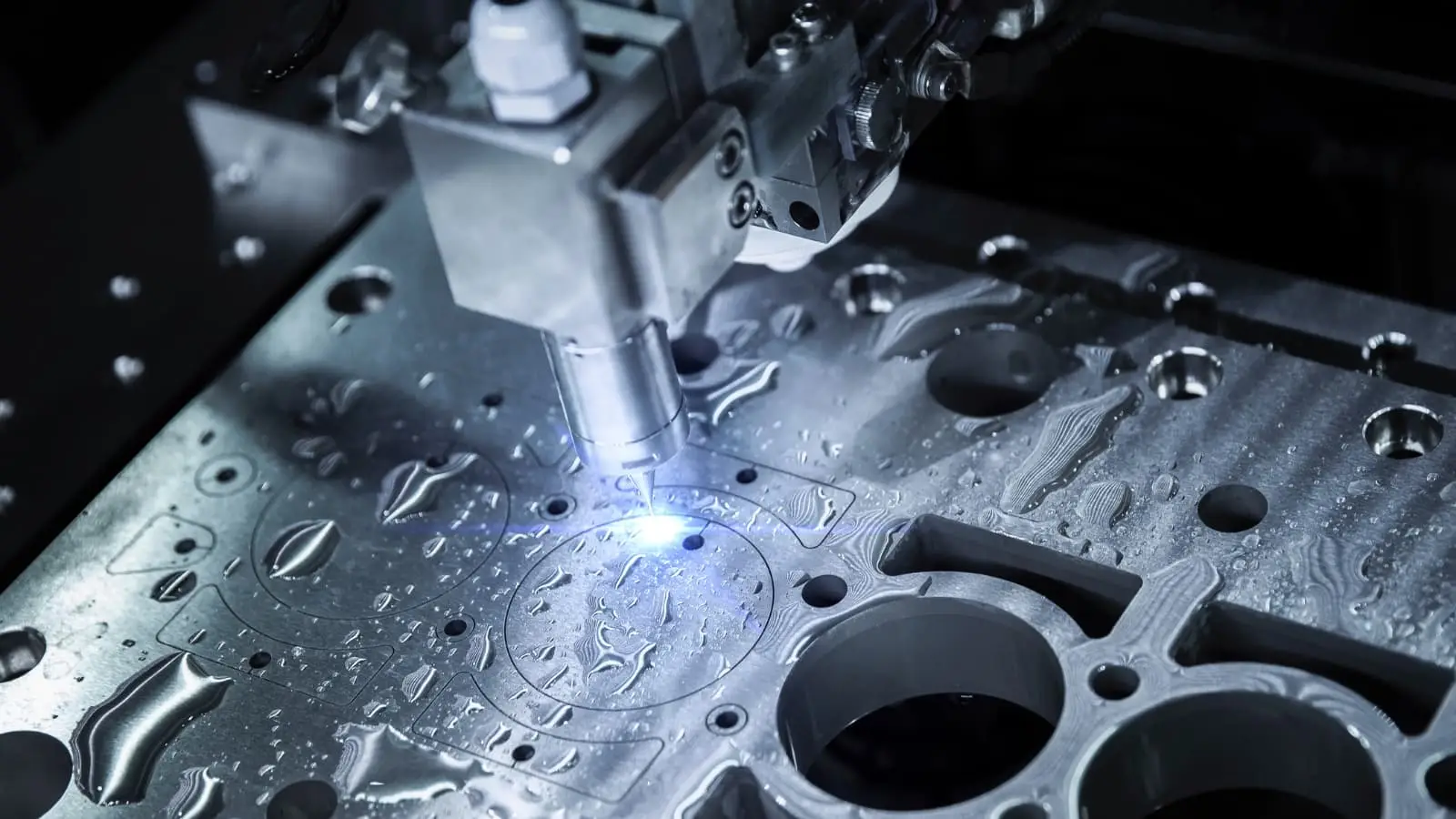
Estimating the exact cost of rotational parts without a formal quote often stalls project timelines and budgeting. Underestimating your machining budget at the design phase usually leads to painful, forced redesigns right before production. Having analyzed thousands of rotational parts and their cost drivers, we broke down exactly how materials, tolerances, and machine time impact your bottom line. Engineers and procurement teams looking for accurate estimates can use this guide to forecast their custom cnc turning cost immediately. Here is the baseline calculator and the exact breakdown you need to optimize your next order.
Core Affect CNC Turning Cost Components
Understanding the exact breakdown of your manufacturing bill helps you identify where to cut costs.
Machine Time (The Largest Variable)
Machine time dictates the majority of your total expense. Complex geometries require slower feed rates. This increases total cycle time and drives up the price.
Standard 2-axis lathes cost less per hour than multi-axis mill-turn centers. Swiss-type lathes operate at different hourly rates but machine long, slender shafts much faster.
Raw Material Expenses
Raw material prices scale based on the specific alloy and the required billet size. Using a steel cnc turning cost calculator requires you to factor in material waste.
Oversized bar stock results in heavy material removal and increased chip waste. Extremely hard materials like titanium also incur a high raw material premium.
Tooling and Wear
Machining hard metals quickly degrades cutting tools. Carbide, ceramic, and diamond (PCD) inserts represent a significant consumable cost.
When turning stainless steel or aerospace alloys, tool wear accelerates rapidly. The factory passes these replacement costs directly to the buyer.
Setup and Labor
Setup costs include programming the toolpaths, preparing the stock, and configuring the machine. For low-volume prototypes, these fixed costs are absorbed by just a few parts.
In mass production, setup time is amortized across thousands of units. This makes the individual piece price drop significantly.
Key Variables That Drive CNC Turning Pricing
Several distinct factors determine the final number on your quote.
Part Complexity: Deep internal bores and thin walls require specialized strategies and slow feed rates.
Tolerances: The standard CNC tolerance is ISO 2768-m (+/- 0.1mm). Requesting precision tolerances of +/- 0.01mm requires slower cutting and frequent tool changes. RapidDirect is capable of high precision up to ±0.003 mm for critical applications.
Batch Size: Ordering a single prototype costs substantially more per unit than a production run of 5,000 parts.
Material Selection: Plastics and aluminum machine easily. Steels and superalloys require more machine time and burn through tools faster.
Delivery Speed: Standard CNC prototyping lead times are 3-5 days. Expedited orders incur rush fees to cover overtime and rearranged production schedules.
Certifications: Medical or automotive parts requiring ISO 13485 or IATF 16949 compliance add administrative and inspection overhead.
CNC Turning Material Cost Multipliers for Faster Estimating
Use this lookup table to adjust your baseline estimates based on material selection.
Material Category
Machinability
Relative Cost Multiplier
6061 Aluminum
High
1.0x (Baseline)
Plastics (POM/PEEK)
Very High
1.1x – 1.5x
Carbon Steel
Medium
1.3x
Stainless Steel
Low
1.6x – 2.0x
Titanium Alloys
Very Low
3.0x – 4.0x+
CNC Turning Cost vs. Other Machining Processes
Procurement teams often weigh turning against other manufacturing methods.
Turning vs. Milling
For axially symmetric parts, turning is significantly faster and cheaper than milling. A lathe continuously cuts the rotating part, removing material highly efficiently. Milling the same cylindrical profile requires complex 3D interpolation and takes much longer.
Standard Lathe vs. Mill-Turn
Standard lathes handle basic cylindrical profiles efficiently. If your part features radial holes or milled flats, a standard lathe requires secondary operations on a milling machine.
Mill-turn centers handle both operations in a single setup. While their hourly rate is higher, the eliminated secondary setup time often results in a lower total cost. RapidDirect offers comprehensive 3/4/5-Axis Milling, Turning, and Mill-Turn services to match the exact needs of your part.
DFM Strategies to Reduce CNC Turning Cost
Engineers can drastically reduce their machining bills by optimizing their CAD files.
Pro Tip: Keep internal corner radii as large as possible. Small internal radii require tiny boring bars that vibrate easily and require very slow feed rates.
Relax Tolerances: Only apply tight tolerances to critical mating surfaces. Leave non-functional features at the standard +/- 0.1mm ISO 2768-m tolerance.
Standardize Threads: Use standard metric or imperial thread sizes. Custom threads require specialized cutting tools and custom programming.
Optimize Wall Thickness: Avoid designing extremely thin walls. Thin walls deflect under cutting forces and require multiple, slow, low-pressure passes.
Simplify Surface Finishes: Specify high surface finishes (Ra 0.8) only where necessary. A standard machined finish (Ra 3.2) requires far less machine time.
Smart Material Swaps: If a part does not experience extreme stress or corrosive environments, switch from stainless steel to aluminum.
How to Estimate Your Precision CNC Turning Cost
You can manually forecast the price using a standard manufacturing formula.
To get an exact figure without manual math, use a digital cnc turning costing calculator. Better yet, submit your drawings for automated quoting.
RFQ Preparation Checklist
Providing incomplete data forces suppliers to pad their quotes for risk. Always include:
Complete 3D STEP files and 2D PDF drawings.
Clear tolerance callouts and surface roughness (Ra) requirements.
Exact material grades (e.g., Al 6061-T6, not just “Aluminum”).
Target order quantities and required lead times.
Required material certifications or inspection reports.
Sourcing CNC Turning with RapidDirect
Traditional quoting takes days and relies on manual estimation. RapidDirect operates an intelligent online platform that features an AI-driven quoting engine, returning prices in minutes.
Our platform provides instant quoting alongside free DFM reports to help you optimize costs immediately. We maintain our headquarters and factories in Shenzhen, China. This location gives us direct access to the supply chain and a lower cost structure, passing the savings on to you.
We hold ISO 9001, 13485, 14001, and IATF 16949 certifications, ensuring robust quality control. You can track your orders in real time, guaranteeing transparency from production to final global shipping.
In CNC machining and custom manufacturing, surface roughness is not merely an aesthetic choice—it is a critical cost driver. Over-specifying tolerances and Ra values is the leading cause of artificially inflated part costs, often increasing manufacturing expenses by over 30%. If surface texture matters to your product’s sealing, friction, or coating adhesion, this guide will help you interpret standard symbols and apply the right specifications without breaking your budget.
This article provides the most comprehensive surface roughness chart and explains how to balance mechanical performance with cost-effective manufacturing. Whether you are sealing a high-pressure valve or prepping a sheet metal chassis for powder coating, RapidDirect’s AI DFM engine can analyze your CAD file in seconds to identify cost spikes caused by overly strict roughness callouts.
👉Jump to Surface Finish Conversion Chart
What is Surface Finish?
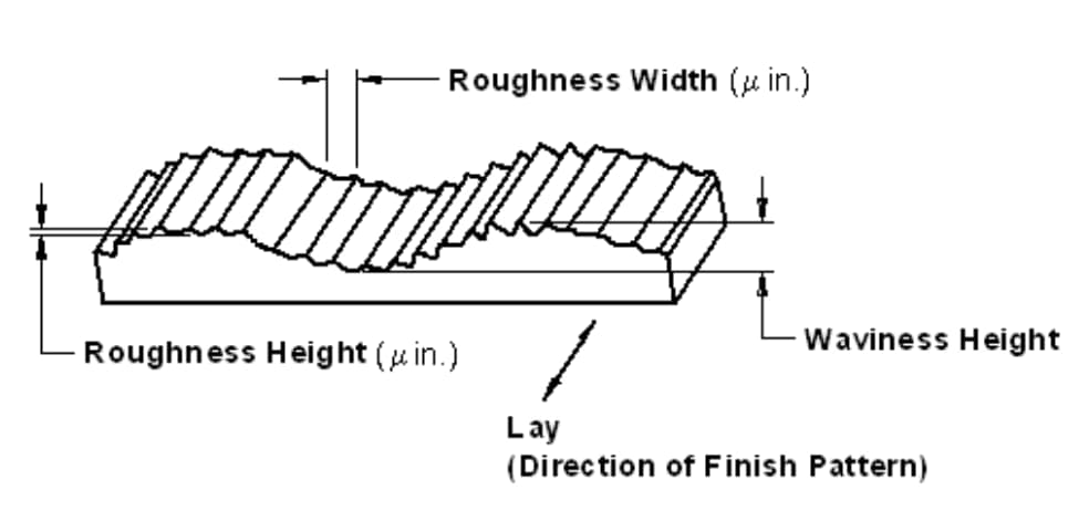
Before we go into the surface finish chart, let’s understand what surface finish entails. Surface finish refers to the process of altering a metal’s surface that involves removing, adding, or reshaping. Surface texture describes a product’s complete surface profile, defined by its roughness, waviness, and lay.
The surface roughness is the measure of the total spaced irregularities on the surface. Whenever machinists talk about “surface finish,” they often refer to surface roughness.
Waviness refers to the warped surface whose spacing is greater than that of surface roughness length. Lay refers to the direction the predominant surface pattern takes. Machinists often determine the lay by the methods used for the surface.
Why is Surface Finish Important in Engineering Processes?
Surface roughness plays a very crucial role in determining how a product reacts to its environment. The finish of a product indicates the performance of its components. Also, the level of roughness may affect the effectiveness of a product.
This depends on the application of such a product. Engineers and manufacturers must maintain surface finish at all times. It helps to produce consistent processes and reliable products.
Surface measurements also help maintain control of manufacturing. It is very useful whenever there’s a need for surface engineering.
Different surface finishes have a variety of effects. The easiest way to get the desired surface finish is to compare it with the surface finish standards. Surface finish can help in the following ways and more:
Incredibly important for corrosion and chemical resistant effects.
It offers a specific visual appeal to the product.
Helps with the adhesion of coatings and paints.
Eliminates surface defects.
Improves conductivity and adds surface electrical conductions.
Increases product’s strength against wear while minimizing friction effects.
RapidDirect is a leading on-demand manufacturing company providing high-quality surface finishing services. We offer 17+ surface finishing processes, including anodizing, powder coating, sandblasting, and more — all designed to enhance both the appearance and performance of your components.
Whether you need a smooth cosmetic look or precise functional finish, our solutions help you achieve the desired Ra surface roughness and durability.
Ready to Start Your Project?
Get Instant Quote
To learn more about surface finishing, read our guide to plastic injection molding surface finish options and read our article about getting the best CNC machining surface finish for your products.
The Broker Trap: Why “Standard” Surface Finish Often Fails
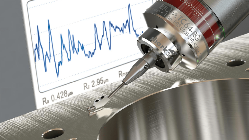
Many digital manufacturing platforms operate as brokers, routing your CAD files to unvetted workshops that lack digital profilometers. Relying on visual or tactile “fingernail checks” to meet a Ra 0.8 µm requirement is catastrophic for precision components such as hydraulic seals, bearing seats, or aerospace housings.
At RapidDirect’s 20,000㎡ proprietary facility, we eliminate this guesswork. We use ZEISS and Mitutoyo surface roughness testers, along with comprehensive CMM verification, to physically verify your specified Ra values. By combining this strict metrology with our high-rigidity 5-axis CNC machines, we consistently achieve ±0.003 mm geometric tolerances and flawless surface finishes, preventing leaks or assembly failures.
How to Measure Surface Roughness
Surface roughness is a calculation of the relative smoothness of a surface’s profile. The numeric parameter – Ra – represents the average roughness. The Ra surface roughness chart shows the arithmetic average of surface heights measured across a surface.
As already mentioned, there are three basic components of a surface, roughness, waviness, and lay. Therefore, different factors are affecting the characteristics of surface geometry.
Likewise, there are several measuring systems for surface roughness. The systems include:
Direct measurement methods
Non-contact methods
Comparison methods
In-process methods
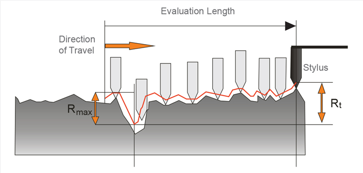
The direct measurement methods measure surface roughness using a stylus. That involves drawing the stylus perpendicular to the surface. The machinist then uses a registered profile to determine roughness parameters.
Non-contact methods involve the use of light or sound instead. Optical instruments like white light and confocal replace the stylus. These instruments use different principles for measurement. The physical probes can then be switched with optical sensors or microscopes.
First, the instrument used will send an ultrasonic pulse to the surface. Then, there’ll be altering and reflection of the sound waves back to the device. You can then assess the reflected waves to determine roughness parameters.
Comparison techniques employ surface roughness samples. These samples are generated by the equipment or process. Then, the manufacturer uses tactile and visual senses to compare the results against the surface of known roughness parameters.
An example of an in-process technique is inductance. This method helps to evaluate surface roughness using magnetic materials. The inductance pickup uses electromagnetic energy to gauge the distance to the surface. Then, the parametric value determined can help find out comparative roughness parameters.
Various Methods of Measuring Surface Roughness
There are different methods and equipment involved in measuring surface roughness. The methods can fall into three categories. They are:
Profiling Techniques. This involves the measurement of the surface using a high-resolution probe. In this process, you need to think more of a phonograph needle in line with sensitivity. A typical CNC probe may not be as effective.
Area Techniques. These techniques measure a finite area of the surface. The measurement offers a statistical average of peaks and troughs in the surface. Some examples of these techniques include ultrasonic scattering, optical scattering, capacitance probes, and more. It is easier to automate and execute with area techniques.
Microscopy Techniques. These qualitative techniques rely on measuring contrasts. The results provide relevant information about peaks and valleys on surfaces.
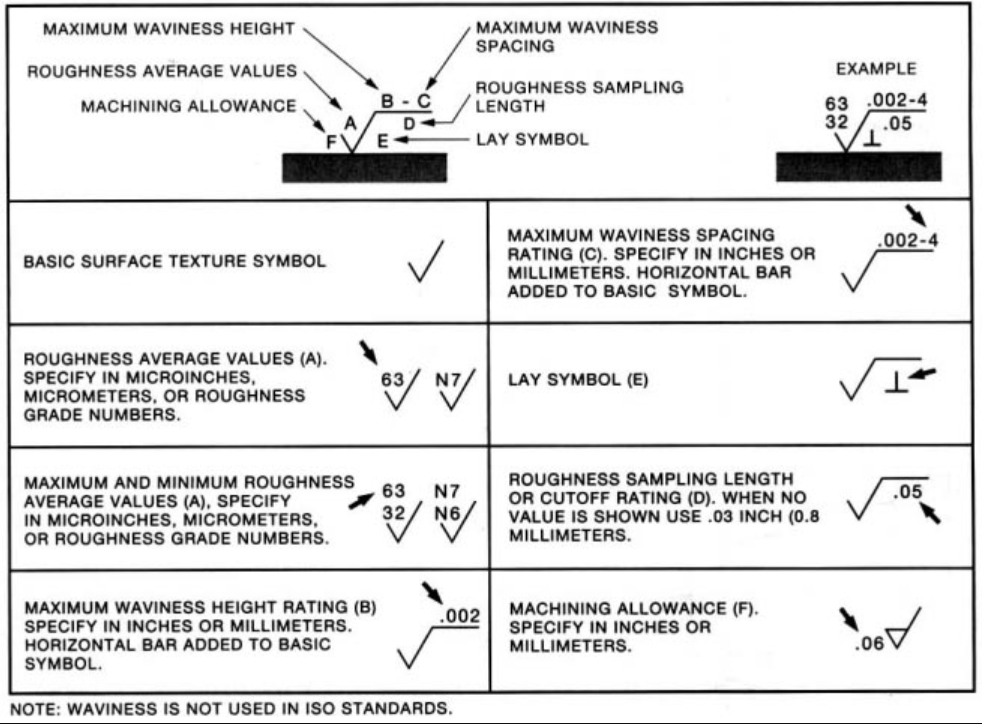
Surface Roughness Symbols Chart and Abbreviations
When you search for machining surface finish symbols on your favorite browser, you would notice a range of abbreviations. These include Ra, Rsk, Rq, Rku, Rz, and more. They are units used in measuring surface finish.
Ra – Average Surface Roughness
While most people refer to Ra as Center Line Average or Arithmetic Average, it is the average roughness between a roughness profile and the mean line. This is the most commonly used parameter for surface finish. The Ra surface roughness scale, often presented as a surface finish chart, shows typical Ra values used in engineering and manufacturing applications.
Rmax – Vertical Distance from Peak to Valley
This roughness parameter is best used for anomalies such as burrs and scratches. It may not be obvious with the Ra surface finish chart though. However, Rmax is a lot more sensitive to those anomalies.
Rz – Average Maximum Height of the Profile
Unlike Ra, Rz measures the average values of the five largest differences between peaks and valleys. The measurement is done using five sampling lengths, and it helps to eliminate error since Ra is quite insensitive to some extremes.
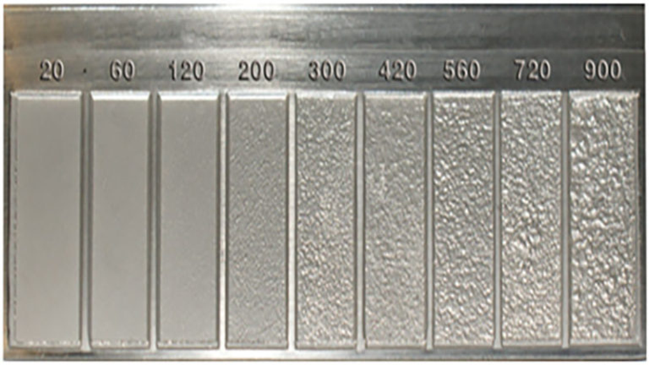
Surface Roughness Chart
The machining surface finish chart offers important guidelines for measuring standard surface finish parameters. Manufacturers always use it as a reference material to ensure quality in the manufacturing process.
20 to 900 RMS
There are different processes in examining the machining surface finish chart. As a result, it becomes challenging to pick the best process based on the performance of the product. However, the most robust is the use of the surface finish conversion chart.
1. Surface Finish Conversion Chart
In this section, you’ll find a table for the surface finish conversion chart. This table serves as a surface roughness comparison chart, helping you compare different roughness scales—such as Ra, Rz, and RMS—across various manufacturing standards and processes. Before diving into the chart, let’s go through some of the abbreviations you’ll encounter.
Ra = Roughness Average
RMS = Root Mean Square
CLA = Center Line Average
Rt = Roughness Total
N = New ISO (Grade) Scale Numbers
Cut-off Length = Length Required for Sample
Ra(micrometers)
Ra(microinches)
RMS(microinches)
CLA(N)
Rt(microns)
N
Cut-off Length(inches)
0.025
1
1.1
1
0.3
1
0.003
0.05
2
2.2
2
0.5
2
0.01
0.1
4
4.4
4
0.8
3
0.01
0.2
8
8.8
8
1.2
4
0.01
0.4
16
17.6
16
2.0
5
0.01
0.8
32
32.5
32
4.0
6
0.03
1.6
63
64.3
63
8.0
7
0.03
3.2
125
137.5
125
13
8
0.1
6.3
250
275
250
25
9
0.1
12.5
500
550
500
50
10
0.1
25.0
1000
1100
1000
100
11
0.3
50.0
2000
2200
2000
200
12
0.3
2. Surface Roughness ChartCheat Sheet
This surface finish ‘cheat sheet’ is a super handy tool to help you better understand the various surface finishes available.
Estimating CNC machining lead times without a finalized quote often leaves project schedules vulnerable to unexpected delays. Underestimating production hours or material sourcing timelines now means painful project extensions and supply chain bottlenecks later. We analyzed thousands of rapid prototyping and production runs to isolate the exact variables that dictate machining schedules. For engineers and procurement managers looking for accurate planning data, this guide breaks down the true timeline drivers. Here is the data and calculation logic you need to keep your assemblies on track.
Standard CNC Machining Lead Times by Order Volume
Before analyzing the specific engineering variables, you need baseline expectations. Standard industry lead times scale directly with order volume and part complexity.
Order Volume
Part Type
Standard Lead Time
Expedited Lead Time
1-5 Parts (Prototype)
Simple
3-5 days
1-3 days
1-5 Parts (Prototype)
Complex
7-10 days
3-5 days
10-50 Parts
Low-Volume
7-14 days
7-10 days
50-500 Parts
Mid-Volume
21-28 days
14-21 days
500+ Parts
Production
28-42 days
21-28 days
Try RapidDirect Now!
Get Quote
What Drives CNC Machining Lead Time?
Part Complexity and Geometry
Every time a machine stops so an operator can reorient a part, lead time increases. Simple parts with single-axis features require minimal programming and a single setup. Multi-sided features, deep pockets, or undercuts require 4-axis or 5-axis indexing.
Complexity scales machining time exponentially rather than linearly.
Rule of Thumb: Design parts to be machined from a single setup whenever possible. Typically, this means confining complex features to one of the six orthographic faces.
Tolerance Requirements and Quality Control
Tight tolerances demand slower feed rates, frequent tool changes, and meticulous metrology. Standard CNC tolerances of ISO 2768-m (±0.1mm) allow for high-speed material removal and rapid spot-checking. Pushing limits to ±0.01mm means operators must take multiple light finishing passes.
Extremely tight tolerances also force facilities to run full Coordinate Measuring Machine (CMM) inspections.
Pro Tip: Only apply tight tolerances to critical mating surfaces. Leave non-functional features at standard tolerances to prevent your parts from spending unnecessary hours in the quality assurance lab.
Material Selection and Machinability
Standard materials like 6061 Aluminum or 304 Stainless Steel are generally kept in stock. They machine predictably and require zero procurement wait time. Exotic alloys like Titanium or Inconel suffer from poor thermal conductivity and rapid work-hardening.
These tough materials require significantly reduced spindle speeds. This routinely turns a standard 10-minute aluminum cut into a 2-hour operation.
Rule of Thumb: If speed is critical, default to aluminum. If a tougher material is required, verify raw stock availability before finalizing the design.
Surface Finishing Delays
Post-processing adds mandatory, non-negotiable days to your timeline. Processes like anodizing, powder coating, or electroplating typically require an additional 7 to 10 days. Parts are often sent to specialized third-party facilities for these treatments. Multiple surface treatments applied to the same part will stack these lead times cumulatively.
Pro Tip: For urgent functional prototypes, request an “as-machined” finish. You can always apply protective coatings locally at a later date.
How to Shorten CNC Lead Times
Automate the Quoting Process
Traditional service bureaus often require 1-2 days just to return pricing and lead time estimates. This delay acts as a bottleneck before manufacturing even begins. RapidDirect’s AI-driven instant quoting engine evaluates your CAD file and returns accurate pricing in under three minutes. This single shift recovers days of idle waiting.
Implement DFM Best Practices
Use standard hole sizes and avoid sharp internal corners to eliminate the need for custom tooling. RapidDirect provides free Design for Manufacturability (DFM) reports instantly upon file upload. This guarantees your design is optimized for the spindle before a purchase order is cut.
Optimize Supply Chain Logistics
Standard global shipping via DHL or FedEx takes 3-5 days. For prototypes, expedited air freight easily offsets the longer transit times. Partnering with a manufacturer based in Shenzhen provides direct access to raw materials and finishing vendors, compressing the overall production timeline.
Summary
CNC lead times are dictated by a combination of geometry, material availability, tolerances, and finishing requirements. By applying DFM principles and standardizing materials, you can drastically reduce both cost and time. Leveraging automated quoting platforms eliminates front-end administrative delays entirely.
Ready to stop waiting days for vendor quotes? Upload your STEP files to the RapidDirect platform today to get instant DFM feedback, precise pricing, and guaranteed lead times in minutes.
CNC machining is one of the core processes in manufacturing that produce intricate and sophisticated products that have applications in various industries. At the heart of CNC machining’s unmatched efficiency and accuracy are the G and M codes – the critical programming languages that guide CNC machines.
Unlike common perception, G codes and M codes hold distinct roles in CNC operations. G codes primarily instruct the machine on the geometry of the cut, while M codes control the hardware aspects, like turning the spindle on or off. This nuanced difference is pivotal for understanding the full potential of CNC machining.
In this article, we delve into the specifics of these codes, unraveling their unique functions and how they synergize to optimize CNC machine performance.
What’s CNC Machining?
Understanding CNC machining is fundamental before delving into the specifics of CNC programming codes. CNC machining, or Computer Numerical Control machining, utilizes computerized controls and machine tools to produce precise and intricate parts from various materials. The technology has significantly transformed the landscape of modern manufacturing as it offers increased efficiency, and accuracy, and can create complex geometries.
Its key advantages are:
Precision: CNC machining offers high precision and accuracy in producing complex parts.
Efficiency: Automated processes and optimized tool paths contribute to efficient material removal.
Versatility: Suitable for a wide range of materials and applications.
Repeatability: CNC machines can produce identical parts with consistent quality.
How Does CNC Programming Control CNC Machines?
Before the advent of computers, machinists used cards or tapes to control machine movements. They punched holes in these cards in a specific order to create the codes. While this was also effective at the time, it was quite tedious. Also, these cards were prone to damage or getting lost in the machine shops. This led to several problems in production at the time.
When machinists started using computers for numerically controlled machines, they still came across a few problems. This was because they had to input the codes manually. This would, of course, be very tedious when they were making quite sophisticated parts that required a lot of instructions.
The advent of advanced computers and software has revolutionized CNC machining. Machinists now simply input instructions into software, which then generates the necessary G codes and M codes for the machines. This process, greatly simplified by CAD and CAM software, has made code generation and machine operation more efficient and accessible, enhancing both precision and complexity in manufacturing.
To start the process, the programmer needs high-level computer-aided software. The programmer then imports the machine model and the machining fixture into the software, then selects the tools and the tooling paths of the spindle. Once these parameters are set, the software efficiently generates the requisite G and M codes, which are essential for the CNC machine to operate effectively.
What Are G-Codes in CNC Programming?
G code (also RS-274D) is the most popular CNC programming language. Most G code commands are in alphanumericformat and start with G which stands for geometry. They are responsible for the movements of CNC machines, telling the machine where to start, how to move, and when to stop when fabricating a part.
However, G code can be quite complicated for machinists because different machines read G codes in different formats. Most machines’ differences are in the presence or absence of spaces between commands and the number of zeros between the letter and number in the commands. For example, a machine might use G3 while another uses G03. Machinists must always be conversant with the type of machine they’re using. Otherwise, errors in the command can lead to serious problems in parts production.
Beyond G codes, programmers use other letters that signify distinct functions as well. These letters diversify the language of CNC programming, enabling a wide range of commands for precise and intricate machining tasks.
A: It directs the tool around the x-axis.
R: It gives the radius of the arcs the machine makes.
X, Y, Z: These three values indicate the tools’ position in three dimensions – X and Y represent the horizontal and vertical dimensions, respectively, while Z represents the depth.
I and J: Both values designate the incremental center of any arc the machine makes.
N: N gives the line number.
The code also uses other letters which depend on the machine’s capabilities.
Block
Description
Purpose
%
Start of program
Start Program
O00001 (Project 1)
Program number (Program Name)
Start Program
(T1 0.25 END MILL)
Tool description for operator
Start Program
N1 G17 G20 G40 G49 G80 G90
Safety block to ensure the machine is in safe mode
Start Program
N2 T1 M6
Load Tool #1
Change Tool
N3 S9200 M3
Spindle Speed 9200 RPM, On CW
Change Tool
N4 G54
Use fixture Offset #1
Move to Position
N5 M8
Coolant on
Move to Position
N6 GOO X-0.025 Y-0.275
Rapid above part
Move to Position
N7 G43 Z1. H1
Rapid to the safe plane, use tool length Offset #1
Move to Position
N8 ZO.1
Rapid to feed plane
Move to Position
N9 G01 Z-0.1 F18
Line move to cutting depth at 18 IPM
Move to Position
N10 G41 Y0.1 D1 F36
CDC left Lead in Line, Dia. Offset #1, 36 IPM
Machine Contour
N11 Y2.025
Line Move
Machine Contour
N12 X2.025
Line Move
Machine Contour
N13 Y-0.025
Line Move
Machine Contour
N14 X-0.025
Line Move
Machine Contour
N15 G40 X-0.4
Turn CDC off with lead-out move
Machine Contour
N16 G00 Z1
Rapid to safe plane
Machine Contour
N17 MS
Spindle Off
Change Tool
N18 M9
Coolant Off
Change Tool
(T2 0.25 DRILL)
Tool description for operator
Change Tool
N19 T2 M6
Load Tool #2
Change Tool
N20 S3820 M3
Spindle Speed 3820 RPM, On CW
Change Tool
N21 M8
Coolant On
Move to Position
N22 X1 Y1
Rapid above hole
Move to Position
N23 G43 Z1 H2
Rapid to safe plane, use tool length, Offset 2
Move to Position
N24 Z0.25
Rapid to feed plane
Move to Position
N25 G98 G81 Z-0.325 RO.1 F12
Drill hole (canned) cycle. Depth Z-.325, F12
Drill Hole
N26 G80
Cancel drill cycle
Drill Hole
N27 Z1
Rapid to safe plane
Drill Hole
N28 MS
Spindle Off
End Program
N29 M9
Coolant Off
End Program
N30 G91 G28 Z0
Return to Machine Home Position in Z
End Program
N31 G91 G28 X0 Y0
Return to Machine Home Position in XY
End Program
N32 G90
Reset to absolute positioning mode (for safety)
End Program
N33 M30
Reset the program to the beginning
End Program
%
End Program
End Program
What Are M-Codes in CNC Programming?
M code, akin to G code, commences with the letter ‘M’ and encompasses a series of auxiliary commands vital for controlling a CNC machine’s non-geometric functions. These codes, often referred to as miscellaneous codes, manage essential operations like halting the program, activating coolant systems, and powering down the machine post-operation.
In CNC programming, it is crucial to use M codes with precision. Typically, each block of program information should contain only one M code. This practice is imperative because M codes often serve to activate or deactivate various machine functions. Overlapping these commands within a single block can lead to programming conflicts and operational errors.
Similar to G codes, M codes vary across different CNC machines. This variance can include differences in the numerical formatting of the codes, such as the inclusion or exclusion of leading zeros. For instance, one machine might recognize an M code as ‘M3’, while another requires ‘M03’. Therefore, machinists must be well-versed in the specific coding requirements of the equipment they operate to ensure seamless and error-free machining processes.
A List of G and M Codes for CNC Machining
This section illustrates a range of basic G and M codes, highlighting their distinct functionalities. While some codes have similar meanings across both lists, others differ significantly in application and interpretation in CNC machining.
Commonly Used of G Codes
G-codes in CNC machining transform complex operations into methodical tasks, with standardized codes ensuring consistency and peak performance. Here’s a look at some key G-Codes crucial for anyone working with CNC machines.
G00 – Rapid Positioning: This command is used for swiftly moving the tool to specified coordinates at maximum speed. Primarily, it positions the tool without engaging in material cutting, optimizing the machine’s efficiency for non-cutting movements.
G01 – Linear Interpolation: This command directs the tool to move in a straight line between two points at a set feed rate. Predominantly utilized for straight-line cutting, G01 is one of the most frequently used G codes in CNC machining.
G02 – Circular Interpolation (Clockwise): This command facilitates the creation of arcs and circles by guiding the tool along a circular path in a clockwise direction. It ensures precise movement to a specified endpoint, essential for circular machining tasks.
G03 – Circular Interpolation (Counter-Clockwise): This command mirrors G02, but with the tool moving along a circular path in a counter-clockwise direction. It’s essential for crafting arcs and circles that require a counter-clockwise approach.
G04 – Dwell: This command instructs the CNC machine to temporarily pause at its current position for a predefined period. The dwell function is particularly useful in scenarios such as allowing a cutting tool to cool down or enabling the spindle to attain the desired speed.
A List of Other Function G Codes
Code
Category
Function
Modal
For Turning or Milling
G17
Plane Selection
XY Plane Selection
Yes
Both
G96
Speeds and Feeds
Constant Surface Speed
Yes
Turning
G91
Positioning and Modes
Incremental Mode
Yes
Both
G03
Circular Interpolation (CCW)
Create arcs and circles (Counter-Clockwise)
Yes
Both
G04
Dwell
Pause for a specified duration
No
Both
G18
Plane Selection
XZ Plane Selection
Yes
Turning
G19
Plane Selection
YZ Plane Selection
Yes
Turning
G20
Unit System
Inch System
Yes
Both
G21
Unit System
Metric System
Yes
Both
G40
Cutter Compensation
Cancel Cutter Compensation
Yes
Milling
For additional information on G codes, please refer to this resource.
Commonly Used M Codes
Although CNC machines typically use M-codes akin to G-codes, standardization across models isn’t universally adopted. Thus, CNC programmers must be cautious about machine-specific codes. Yet, certain M-codes consistently retain the same meaning across all machines.
M00 – Program Stop: To stop the CNC program temporarily. It often requires operator intervention to resume the program.
M02 – Program End: To end the CNC program. After executing this code, the control will stop, and the operator may need to reset or restart the machine.
M03 – Spindle On, clockwise: To start the spindle rotation in the clockwise direction. It is often followed by a speed command (S) to set the spindle speed.
M04 – Spindle On, Counterclockwise: Similar to M03, M04 is used to start the spindle, but it rotates in the counterclockwise direction.
M05 – Spindle Stop: To stop the spindle rotation. It is often employed when a tool change or other operation requires the spindle to be stationary.
A List of Other Function M Codes
Code
Category
Function
Modal
For Turning or Milling
M08
Coolant
Coolant flood or on
No
Both
M42
Auxiliary Functions
High Gear Select
No
Turning
M19
Spindle Control
Change spindle orientations
No
Milling
M00
Program Control
Program Stop
No
Both
M02
Program Control
Program End
No
Both
M03
Spindle Control
Spindle On, Clockwise
No
Both
M04
Spindle Control
Spindle On, Counterclockwise
No
Both
M05
Spindle Control
Spindle Stop
No
Both
M06
Tool Change
Tool Change
No
Both
M09
Coolant
Coolant Off
No
Both
For additional information on M codes, please refer to this resource.
Let’s Summarize The Difference Between G and M Codes
G-codes:
Direct the motion and function of the CNC machine.
Describe positions and movements, such as rapid positioning to a specific XY plane, linear feed movement, and circular interpolation.
Related to geometric codes, serve in product design.
Activate the CNC machine.
M-codes:
Control operations not involving movements, such as stopping programs, changing tools, turning the spindle on or off, and activating coolant systems.
Relate to machine functions and serve in various miscellaneous operations.
Activate the machine’s programmable logic controller (PLC).
RapidDirect’s Expertise in CNC Machining
Explore CNC machining solutions with RapidDirect, where understanding and precision meet. Our team is skilled in the intricacies of G and M codes, ensuring that every project is handled with attention to detail and expertise. We believe in offering high-quality results that are both effective and affordable.
Our user-friendly platform streamlines your experience, offering instant quotations and a straightforward project tracking process. Managing your CNC machining needs becomes effortless with our efficient and accessible system.
Wondering aboutCNC machining and why it’s a big deal in the manufacturing world? You’re not alone. Computer Numeric Control (CNC) Machining is a key player in modern manufacturing, using advanced technology to cut, shape, and create parts with precision.
This article breaks down the basics of how CNC machines work and their role in making everything from car parts to tech gadgets. We’ll also look at the many industries that rely on this technology and why it’s so important.
Overview of CNC Machining
CNC machining, controlled by computers, produces high-precision parts and components. In this process, a computer program controls the movement of the cutting tools, which the CNC programming controls to remove material from a workpiece to create a finished part.
CNC technology produces an array of parts and components, including those made from metal, plastic, and other materials. The process can also produce parts with complex geometries and high levels of precision, making it a popular choice for applications in numerous industries, including aerospace, automotive, medical devices, and consumer products.
It offers several advantages over traditional machining methods, including improved accuracy, consistency, and speed, as well as the ability to produce complex geometries and intricate details. It also allows for the use of advanced cutting tools and techniques, such as multi-axis machining centers and high-speed machining, which can further improve the efficiency and quality of the process.
The History of CNC Machining
Its history can be traced back to the 1940s when the first numerical control (NC) machines were developed. Over time, these machines became more widespread and sophisticated. This gave them the capability to fulfill the requirements of a variety of industries including aerospace, automotive, and defense.
However, older NC machines still needed manual input and had limited capabilities.
The transformation of manufacturing began in the 1970s with the introduction of computers, leading to a breakthrough: the first CNC machines. These advanced machines, equipped with computer controls, could process data with unprecedented speed and accuracy. This innovation allowed CNC operators to input commands directly into the machine, which then automatically executed the necessary operations, significantly streamlining the manufacturing process.
This was only the beginning of CNC machines as the technology continued to advance over the years. The development of more advanced software and hardware along with the introduction of new material and tooling options meant more possibilities for manufacturing units.
Today, CNC machinery is common in multiple industries and is capable of producing a diverse range of products with high levels of accuracy and precision.
How CNC Machining Works?
Contemporary CNC systems focus on minimizing human intervention as much as possible. This ensures consistent and continuous performance, which facilitates smart manufacturing and delivers excellent results.
However, CNC manufacturing requires careful consideration from the initial design to the final manufacturing. The entire process works in three different steps:
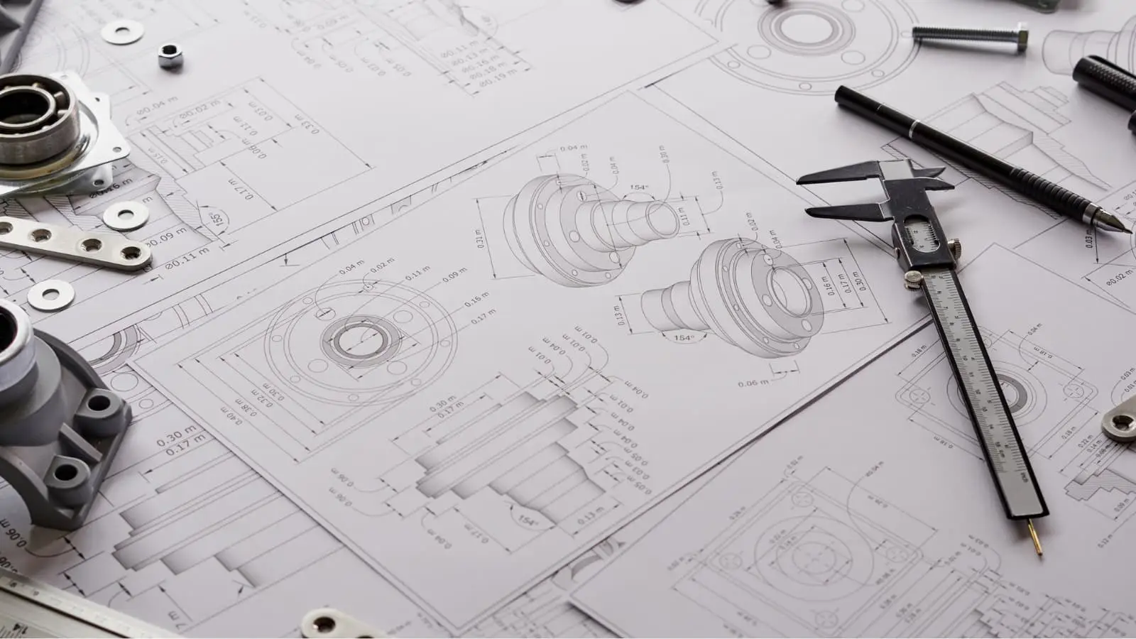
1 – Design
The first crucial step in CNC machining involves software applications like CAD, CAM, and CAE. Engineers and designers rely on these tools to design parts and products, and then assess their manufacturability. This assessment, known as Design for Manufacturing (DFM), is vital. It ensures that the design is optimized to maximize efficiency and reduce costs, all while working within the constraints of existing technology.
In most cases, the CAD tools available in the market come with an internal CAM tool, which facilitates the pre-processing and programming.
After finalizing the CAD design, the designer converts it into a CNC-compatible file format, typically STEP or IGES.
2 – Pre-processing and Programming
CNC machine programming primarily involves using G-codes and M-codes to communicate with machines. These codes, generated by CAM packages, act as a guide for the cutting tool’s path in CNC operations.
Usually, if a design adheres to DFM (Design for Manufacturing) standards, CNC machinists don’t need to intervene in the pre-processing or operational stages. However, if the design doesn’t meet these standards, some level of manual intervention may be required to guarantee optimal performance.
Pre-processing is a standard step in CNC machining, and its duration depends on the design’s quality. Programming the G-Codes or M-Codes typically takes just a few minutes. However, the success of CNC programming hinges on the design’s adherence to DFM conventions. Accurate designs produce correct codes and satisfactory results, while design flaws lead to erroneous codes and poor outcomes.
3 – Machining
The final stage is the machining process, which uses the provided codes from the previous step to remove excess material from a block.
Precision in machine tooling is crucial, yet it’s often challenging to replicate the exact dimensions of a CAD model. This is why machinists typically apply standard ISO 2768 tolerances, which vary based on industry requirements. It’s a widely accepted principle that tighter tolerances lead to increased manufacturing costs.
Common CNC Operations Across the Industry
CNC machining is a versatile process with operations varying based on specific requirements. Simple designs might be achieved through a single operation, such as milling. However, more complex designs typically require a greater variety of operations.
Below are some key CNC machining equipment widely used in the industry.
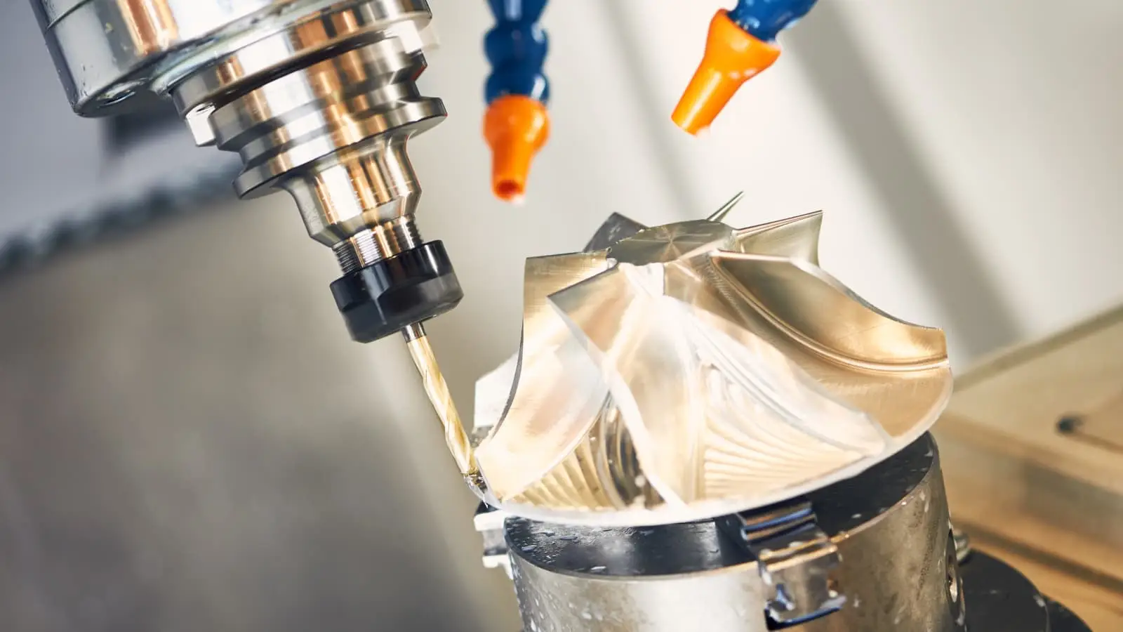
CNC Milling
CNC milling is a highly precise and versatile machining process used to remove material from a solid block to create a specific shape or design. It involves the use of a CNC system to manipulate a multi-point cutting tool, typically a milling cutter, with extreme accuracy. During this process, the workpiece is securely mounted on a table, and the milling cutter is rotated at high speeds to systematically chip away at the material. This method is particularly effective for generating flat surfaces, but its capabilities extend far beyond simple shapes.
One of the key features of CNC mills is their ability to perform intermittent cutting with multiple machine steps, allowing for the efficient creation of complex geometries. The technology has evolved to include 3, 4, and 5-axis milling machines:
3-Axis Milling: Movements along the X, Y, and Z axes enable basic operations like drilling and planning. Ideal for straightforward projects requiring simple shapes, this method is popular for its simplicity. However, it’s limited in creating complex geometries, making it best suited for less intricate designs.
4-Axis Milling: Adding a rotational axis, allows for more complex operations than 3-axis milling. This method is ideal for angular cuts and more intricate shapes, expanding the capabilities of CNC machining. It’s particularly useful for parts requiring additional precision that 3-axis milling machines can’t provide.
5-Axis Milling: The pinnacle of CNC milling, this type of machining method moves along five axes simultaneously, allowing for extreme precision and complexity. It’s invaluable in high-precision industries for creating complex shapes with tight tolerances. This method streamlines production by reducing the need for multiple setups, ensuring efficiency and accuracy.
CNC Turning
CNC turning is a highly efficient machining process predominantly used for shaping cylindrical workpieces, although it can also handle square or hexagonal-shaped raw materials. At its core, CNC turning involves the use of a computer-controlled lathe that rotates the workpiece against various cutting tools. These tools trim and shape the material into the desired cylindrical form.
The uniqueness of the turning machine lies in its versatility and precision, governed by different spindles and speed capabilities. This process can be performed on both vertical and horizontal setups, each catering to specific types of workpieces and machining requirements.
There are two main types of machines:
CNC Lathes: It excels in precision turning operations, ideal for crafting cylindrical parts with high accuracy. It operates by rotating the workpiece against a stationary tool, making it perfect for simple to moderately complex shapes, commonly used in automotive and aerospace industries.
CNC Turning Centers: It combines turning with additional functions like milling and drilling. This multi-tasking capability allows for producing complex parts in a single setup, enhancing efficiency and accuracy. It’s essential in industries requiring intricate, multifaceted components, such as advanced manufacturing.
CNC Drilling
Drilling is an important manufacturing process that creates different-sized thread holes in a workpiece. The process is completely automated because of the involvement of a computer that precisely controls the movement and speed of the drill bit.
CNC drilling is quite common in many industries including printed circuit boards, metal parts, and plastics. The process offers several advantages over traditional manual drilling, including increased accuracy, repeatability, and efficiency.
CNC Routing
The crude operations of CNC routers are the same as milling machines. Routers generally deal with softer materials like wood while milling is common for tougher metals. Just like any CNC operation, routers also deliver excellent consistency, efficiency, and accuracy.
In the routing process, the workpiece remains completely stationary while the spindle moves in different directions. Since the routing process is for softer materials, the overall rotating speed of the spindle can be quite low. There are numerous CNC routing machines, including benchtop routers, gantry routers, and moving gantry routers. The choice of machine and cutting tool will depend on the specific requirements of the workpiece and the desired end product.
Electric Discharge Machining
An electric discharge machine (EDM) is a manufacturing process that utilizes electrical spark discharges to erode material and produce complex shapes and geometries.
The process works by creating a spark between an electrode and the workpiece. The machinists submerge the workpiece in a dielectric fluid, which isolates the electrical energy and allows for the precise control of the spark. The spark discharge vaporizes the workpiece and removes access material to obtain the required shape.
There are two main EDM types: sinker EDM and wire EDM. Sinker EDM uses a consumable electrode to create the spark. Contrarily, wire EDM uses a thin wire that moves to and fro to create the spark.
CNC Plasma Cutting
CNC plasma cutting is a dynamic manufacturing process widely used in large-scale industrial settings, renowned for its ability to make high-speed and precise cuts in electronically conductive materials like steel, stainless steel, aluminum, brass, and copper. This method involves a plasma torch that creates a powerful plasma arc between an electrode and the workpiece, effectively melting and vaporizing the material at the point of contact. A critical component of this process is the high-pressure stream of gas, such as air or nitrogen, which expels the molten material from the cut area, resulting in a clean, precise edge with minimal deformation or discoloration.
This technique stands out for its versatility, seamlessly cutting both thin and thick materials, which broadens its industrial applications. Moreover, plasma cutting is cost-effective, offering lower operational costs compared to other methods. Its integration of speed, precision, and affordability makes it an essential tool in modern manufacturing, particularly in industries where efficiency and accuracy are crucial.
CNC Laser Cutting
CNC laser cutting, a staple in industrial manufacturing, is celebrated for its precision and speed. It employs advanced lasers, including CO2, Nd, and Nd: YAG types, to effectively vaporize materials, ensuring clean and precise cuts. This technology is versatile enough to handle a wide range of materials, contributing to its widespread use across various industries.
The technology’s precision is not just limited to single operations; it excels in repeatability, which is essential for mass production. This consistent accuracy is particularly beneficial in sectors like aerospace and automotive, where exactness is crucial. CNC laser cutting is also known for its efficiency, resulting in minimal material wastage and superior precision. Furthermore, the process simplifies work holding and reduces workpiece contamination, enhancing overall productivity. With its ability to create finely detailed cuts and maintain strict tolerances, it stands as an indispensable tool in contemporary manufacturing.
Types of CNC Machines: A Brief Intro
The capabilities of CNC machines vary widely, influenced by their complexity and cost. Some machines are versatile, performing a range of operations, while others are specialized for specific tasks. Below are the most common types of CNC machines prevalent in the industry:
3 Axis, 4 Axis & 5 Axis Machines:
Milling Machines: They perform complex material removal using various tools, including lathes and water jets. Operating across multiple axes—horizontal, vertical, and angled—these machines handle detailed milling of wood, metal, and plastic, enhancing efficiency by minimizing material repositioning.
Turning Machines:
Turning processes involve securing material on a rotating mechanism, typically a lathe. As the material spins, a CNC tool removes small amounts to achieve desired shapes, effectively crafting cylindrical and tapered components with precision and consistency.
CNC Routers:
Designed for precision, CNC routers cut and shape materials like wood, plastic, and metal, delivering intricate 3D designs for industries that demand detailed patterns and high accuracy.
Surface Grinders:
CNC grinding machines produce superior surface finishes with abrasive wheels. This subtractive process achieves remarkable precision, reducing surface imperfections to tolerances as fine as 0.1 millimeters, making it a preferred choice for high-quality surface treatment.
EDM Machines:
Advanced cutting methods include Sinker EDM and Wire EDM. Sinker EDM uses controlled thermal erosion with electrodes in a dielectric fluid, while Wire EDM employs fine wire electrodes for intricate, detailed cutting.
Plasma Cutters:
Using high-temperature plasma, these machines efficiently slice through conductive materials such as steel and aluminum, offering fast and precise results for industrial metalworking projects.
Laser Cutters:
Focused laser beams allow for clean, intricate cuts and engravings on metals, plastics, and glass, making them perfect for applications in aerospace, jewelry, and electronics.
CNC Machining Parameters
CNC machining is known for its precision and versatility, guided by parameters set during G-code generation. At RapidDirect, our CNC milling systems can handle parts with dimensions up to 4000 x 1500 x 600 mm (157″ x 59″ x 24″), offering a build area significantly larger than that of 3D printers. For CNC turning, we are equipped to machine parts with diameters up to 200 mm (7.9″), accommodating a diverse range of component sizes. Our CNC machines are capable of achieving outstanding precision with tolerances as tight as ±0.001 inches (±0.025 mm), which is less than half the diameter of an average human hair. RapidDirect is equipped to meet your needs with a typical lead time of 5 business days, and 1-day delivery for simpler parts. We are committed to delivering precision and efficiency.
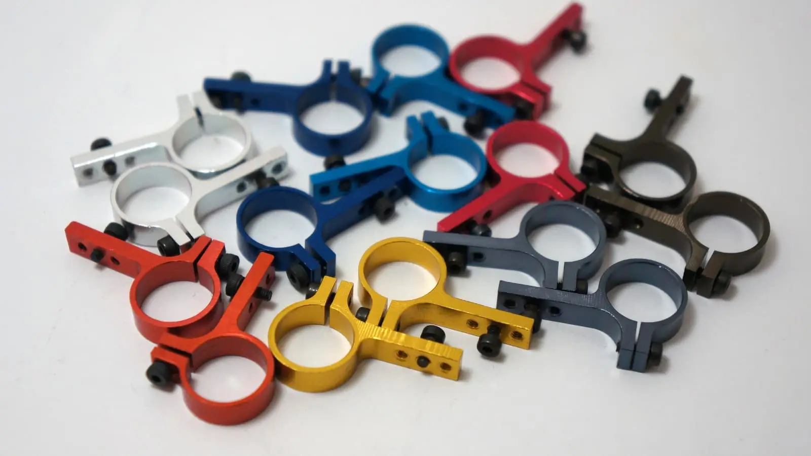
Common CNC Materials and Surface Finishes
Here’s a brief list of common CNC materials:
Stainless Steel
Aluminum
Titanium
Copper
Brass
Other Steel Alloys
Plastics
Here’s a list of common CNC surface finishes:
As machined
Sand blasting
Powder coating
Anodizing
Painting
Polishing
Heat Treatment
Brushed Finish
Black Oxide
Common Applications of CNC Machined Parts
Machining processes, known for their precision in fabricating CNC parts, are utilized in various capacities across numerous fields. The industries that benefit most significantly from the capabilities of CNC machining include:
Industry
Applications
Aerospace
Ammunition, and other similar items.
Automotive
Engine parts, transmission components, and suspension components.
Medical Devices
Implants, prosthetics, and surgical instruments.
Consumer Products
Electronics, toys, and common household items.
Machinery and Equipment
Pumps, valves, and gears.
Prototyping and R&D
Produce prototypes and test parts for research and development purposes.
Jewelry Production
Intricate jewelry requires precision and repeatability
Molds and Dies
Molds and dies are necessary for producing plastic and metal products.
Main Pros and Cons of CNC Machining
Here are the main advantages and disadvantages that CNC machining offers:
Advantages
Disadvantages
It allows for precise control of the cutting tool, resulting in parts with tight tolerances and excellent repeatability.
CNC machines are quite expensive. Moreover, there are many types of them and most of their operations are not interchangeable. Thereby making capital requirements significant for small and medium businesses.
It can operate at high speeds, allowing for faster production of parts.
Trained operators needed: Unlike traditional machines, CNC operators require significant training before they can start working. Which means they are more in demand and have higher wage requirements.
It ensures consistent quality, which is excellent for a consumer product or large-volume production.
While efficient, some CNC operations may waste more material compared to the manual process. However, the precision, repeatability, and efficiency they offer may offset this con in many cases.
It offers the flexibility to create a wide array of parts, ranging from simple to intricate designs, with effective programming and the right machining approach.
It ensures consistent quality, which is excellent for a consumer or large-volume production.
It is cost-effective for large production runs, leveraging economies of scale to lower the cost per piece, meeting industry demands for efficiency and affordability.
It offers enhanced safety compared to manual methods, as operators control the machines remotely, reducing exposure to hazards like shards, heat, and other threats.
Since most of the processes are automatic, they are optimized to perform consistently without any intervention. Thereby lowering the overall maintenance requirements.
CNC Machining Parts with Complex Geometries: Key Design Restrictions
When designing CNC machined parts with complex geometries, understanding the limitations of the machining process is crucial for achieving the desired results. Unlike 3D printing, where intricate shapes can be produced without significant cost increases, CNC machining becomes more expensive as part complexity rises due to additional setup and processing steps. The primary limitations stem from the geometry of the cutting tools, which are typically cylindrical and restricted by their cutting length, making sharp internal corners difficult to achieve.
Another key factor is tool accessibility. While 3-axis machines can only work on features that are directly accessible from above, 5-axis systems offer greater flexibility by allowing the tool and part to move in multiple angles. This capability enables the machining of areas that are otherwise unreachable on 3-axis systems. Additionally, parts with thin walls pose a challenge because they are susceptible to vibrations and may break under machining forces.
Considering these constraints while designing for CNC machining ensures that parts are both manufacturable and of high quality.
RapidDirect: The Right Manufacturing Partner for Every CNC Project
Meeting CNC manufacturing needs, especially for small or medium-sized businesses, can be resource-intensive, necessitating expertise in machining parts and CNC certification. To address these challenges, partnering with specialized CNC machining providers like RapidDirect has become a prevalent industrial practice.
RapidDirect stands out as an ideal manufacturing partner, offering top-tier CNC machining services. Operating from China, a global manufacturing hub, the company has a proven track record of excellence. Their expert team is capable of achieving tolerances as precise as 0.01mm, encompassing a range of services such as CNC turning services, CNC milling services, plasma cutting services, and laser cutting services.
Moreover, RapidDirect is not only ISO 9001 certified but also boasts a state-of-the-art quality control process, ensuring the highest standards of customer satisfaction with every project. This combination of expertise and quality assurance makes them a reliable choice for addressing diverse CNC machining requirements.
Start Your CNC Projects Today!
With cutting-edge technology and expert craftsmanship, we’re here to bring your innovative designs to life.
Try RapidDirect Now!
Get Quote
Bonus: What’s It Like to be a CNC Machinist?
Being a CNC machining is not easy. It’s a tough and demanding job requiring a lot of creativity, dexterity, and quick thinking. Moreover, CNC machining is evolving and it’s the machinist’s job to keep up with the new updates and deliver the best the current technology has to offer.
Here are the few expectations that come with the role of a CNC operator:
Hands-on knowledge: It’s important to understand the inner workings of the machines and perform basic diagnostics. CNC machinists spend much time with different cutting tools and need excellent hand-eye coordination.
Technical skills: A basic level of understanding of machine tools, fixtures, and design philosophies is critical.
Problem-solving: CNC operations are automated but may encounter any issues as well. The operator must know enough basics to deal with the problem and rectify basic issues easily.
Programming skills: The only way to communicate with a CNC machine is through the program. So, it’s necessary to have the necessary programming knowledge.
Attention to detail: Precision is a basic requirement for any machining project and any operator must have the right attention to detail for the best performance.
Conclusion
CNC machining stands as a cornerstone in modern industry, sparking curiosity among those outside the field. It’s a key driver of the industrial age and is poised to play a significant role in the future.
The rise of SMART factories and Industry 4.0 hinges on CNC machining capabilities. This technology bridges manual machining with digital control, ensuring unparalleled precision and consistency. While the manufacturing technique has some limitations, its benefits far outweigh these challenges. As the technology evolves, current issues are expected to be resolved, further enhancing its impact.
Interested in experiencing top-notch CNC machined outcomes? Reach out to RapidDirect today and discover the excellence of advanced CNC solutions!
FAQs
1. What are the ideal uses for CNC machining?
CNC machining is highly effective for producing precise, high-quality parts used in industries such as aerospace, automotive, medical devices, and electronics. It’s ideal for creating complex geometries and tight tolerances that manual machining cannot achieve consistently.
2. Which cutting tools are commonly used in CNC machining?
CNC machining typically employs a range of cutting tools including end mills, drills, lathes, and taps. Each tool is chosen based on the material and the specific cutting operation, allowing for efficient and accurate material removal.
3. Is CNC machining fully automated?
While CNC machining is largely automated, it still requires human oversight for setup, programming, and quality control. Automation enhances efficiency and precision, but skilled operators are crucial for optimizing performance and addressing any issues.
4. What surface finish can be expected from CNC milling and turning?
CNC milling and turning generally produce a smooth surface finish, though the exact texture can vary depending on the material and the machining parameters. Finishing processes like sanding or polishing may be applied for enhanced smoothness and appearance.
5. How can CNC manufacturing speed be increased?
To accelerate CNC manufacturing, optimize machine settings such as feed rates and cutting speeds, use high-performance tooling, and implement advanced technologies like automated material handling. Regular maintenance of machinery also helps maintain efficiency and reduce downtime.